4 | Installation and commissioning
44
D-ISC 100 x xx2
cannot be operated without (Dc). Note: The operation of multiple
D‑ISC100s within one sensor network is only possible from
D‑ISC100 firmware version 02.02R0000.
Parameterisation
When parameterising a sensor system with this architecture, pro-
ceed as follows:
● Set the "network mode" for each D‑ISC100:
D‑ISC100 Network mode
(Da) D‑ISC100 network
(Db) and (Dc) Sensor network
● Allocate the correct sensor position to each sensor in the user
interface of the corresponding D‑ISC100. Start with the con-
figuration of (Db).
D‑ISC100 Sensor Sensor position
(Db) (Sa) S1
(Dc) (Sb) S1
(Da)* (Sa) S1
(Sb) S2
*(Da) access to (Sa) is performed via the Modbus address of
(Db).
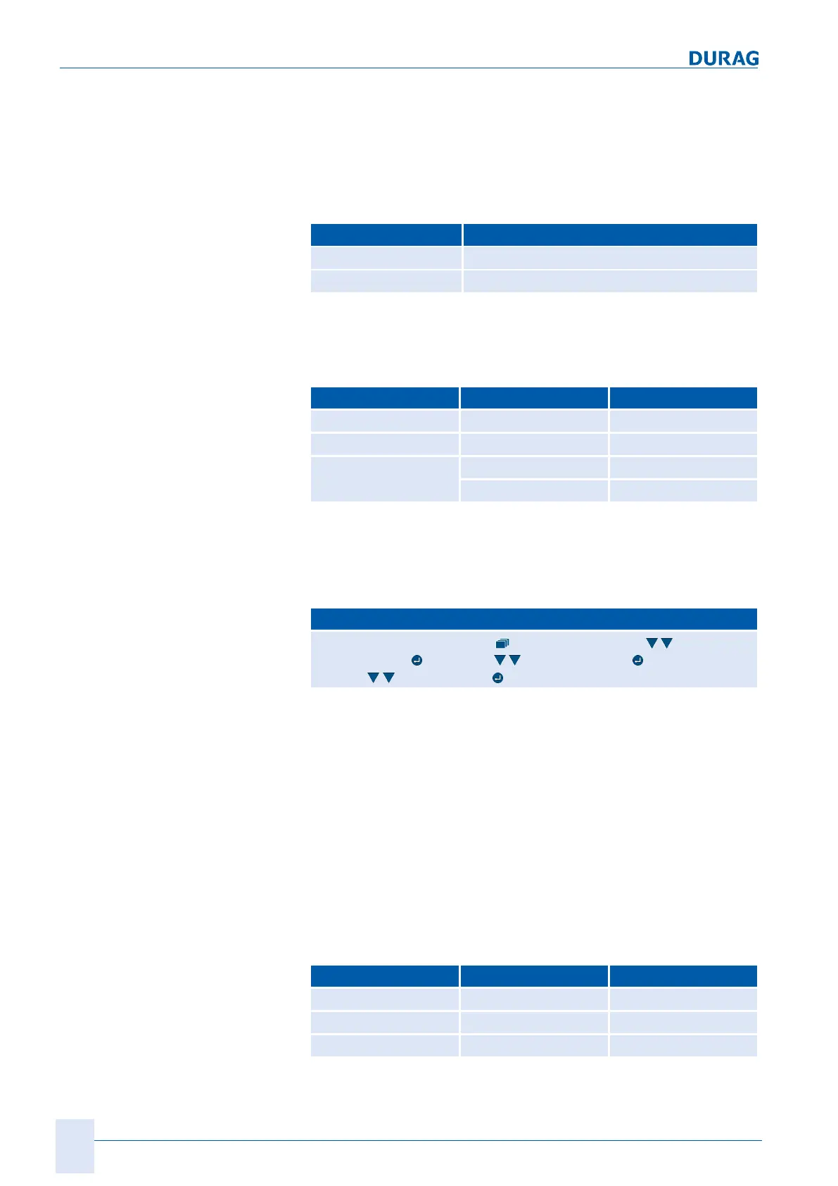
This path will take you to the required menu:
D‑ISC100 menu path:
Standard display (e.g.: S1.1) User mode (menu1) System
setup (menu3)
Date/Time DURAG Modbus Communication
Settings
Network mode
Power supply
A D‑ISC100 can supply a sensor with the necessary operating
voltage. The D‑ISC100P also supplies the necessary purge air.
In the example, the D‑ISC100 (Db) is supplying sensor Sa with
voltage, and the D‑ISC 100 (Dc) is supplying sensor Sb with
voltage. The connecting cables to the sensors (Sa and Sb) are
pre-wired at the terminals of the D‑ISC100. There are connect-
ors on the other ends of the cables. The sensors are connected
exclusively via this connector. The operator does not need to
carry out any local wiring work on the terminals.
Communication
Communication between the D‑ISC100 and the sensors is per-
formed via a serial Modbus connection. The following applies
here:
Modbus Master Slave
C (Db) (Sa)
D (Dc) (Sb)
B (Da) (Db) and (Dc)
 Loading...