3 | Device and Function description
26
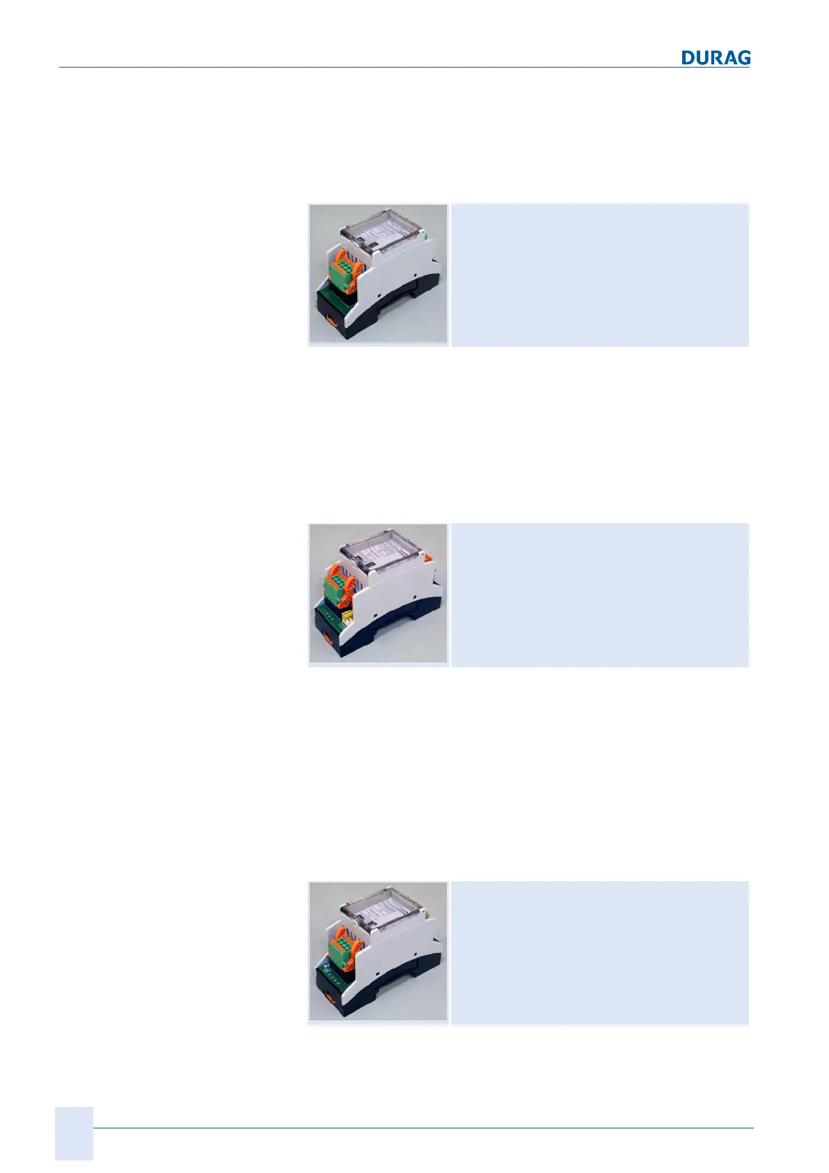
D-ISC 100 x xx2
● 4 x analogue output 0-20mA/400 Ohm
● Zero point (live zero) 4mA
The analogue output expansion module allows the determined
measured values from the D‑ISC100 to be issued as current sig-
nals.
Analogue input (AI)
Top hat rail expansion module
see also 4.3.3 Analogue input [}52]
An optional analogue input expansion module D‑ISC100 (mod-
ule - analogue IN) is available for 4 additional analogue inputs
per device.
● 4 x analogue input 0-20mA/50 Ohm
● Zero point (live zero) 0/2/4mA, adjustable
The analogue input expansion module allows external sensors
with current output (e.g. temperature sensor) to be connected to
the D‑ISC100.
Digital output (DO)
Top hat rail expansion module
see also 4.3.6 Digital output [}56]
Two
digital outputs DO0 are integrated into the universal opera-
tion unit.
An optional digital output expansion module D‑ISC100 (module -
digital OUT) is available for 8 additional digital outputs per
device.
● 8 x relay output, potential-free, 48V, 0.5A
● Configurable function
The digital output expansion module allows the status (e.g. main-
tenance mode, zero point measurement, 0/1) to be issued by the
D‑ISC100.
Digital input (DI)
Top hat rail expansion module
see also 4.3.5 Digital input [}55]
An optional digital input expansion module D‑ISC100 (module -
digital IN) is available for 8 additional digital inputs per device.
 Loading...