4 | Installation and commissioning
34
D-ISC 100 x xx2
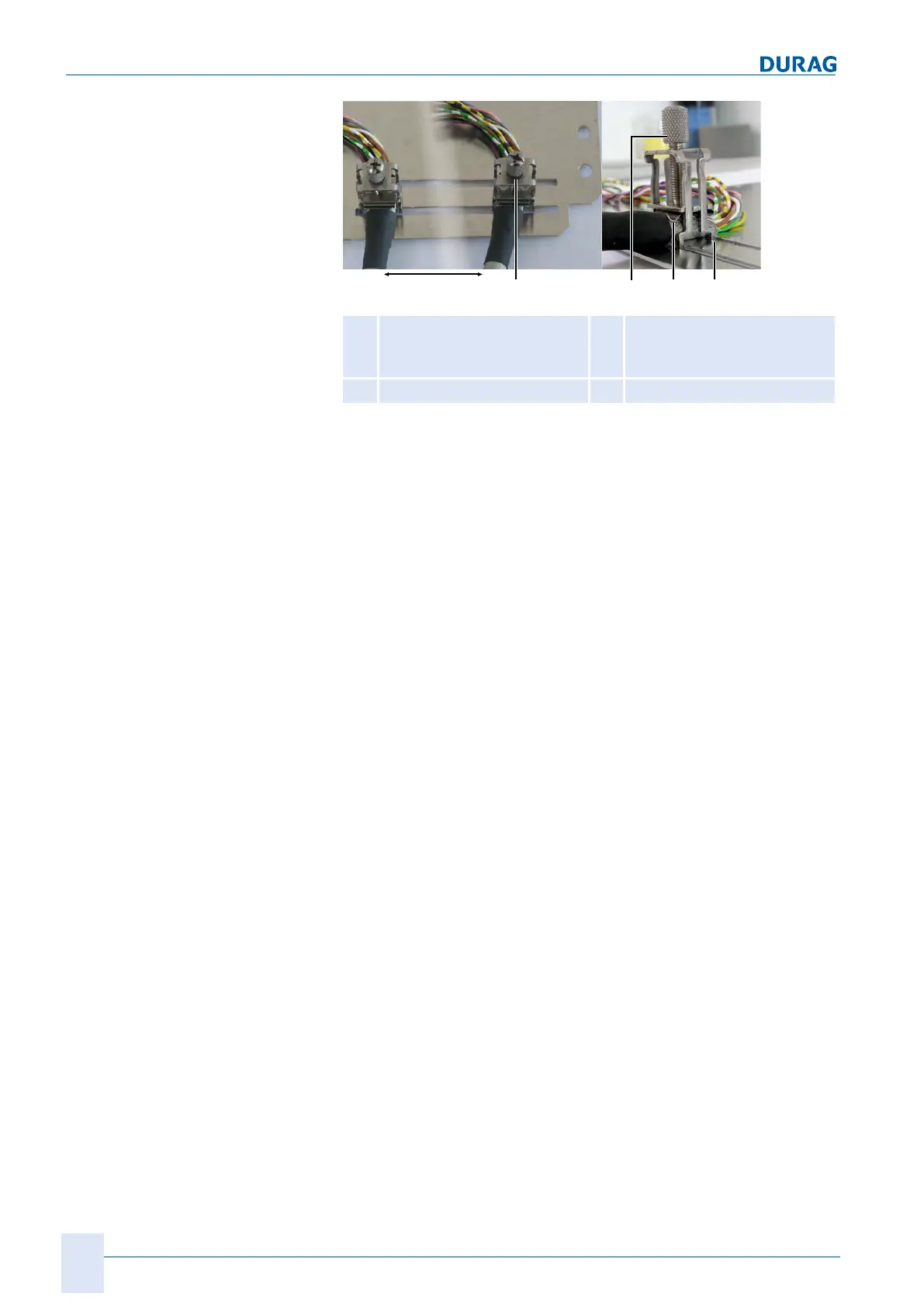
Data cable connection
01
Loosen/tightly screw in the
knurled screw
02
Moving the terminal
03
Shield terminals
04
Terminal holder
Fig.4.1: Shield terminals
1.
Strip back approx. 20 mm of the outer insulating layer of the
data cable above the screen in addition to the free cores.
2.
Guide the data cable through the cable gland of the Universal
control unit and lay it onto the base plate in the required posi-
tion (see top right image).
3.
Click the shielding terminal above the stripped back cable
shield with the terminal holder (04) into the guide rail in the
base plate.
4.
Use the knurled screw (01) to simultaneously secure both the
terminal in the guide rail and also the shielding between the
shield terminal (03) and the base plate.
✓ If the knurled screw is loosened, the terminal can be
moved to any position on the rail (02).
✓
Always connect both ends of the shielding.
✓ To remove the terminal, the knurled screw is screwed com-
pletely upwards. The terminal holder (04) is spread apart
by the shield terminal which is also guided through, and the
terminal can be pulled out of the rail.
5.
Connect the wires in accordance with the connection dia-
gram.
 Loading...