5 | Basic operation of the D-ISC 100
D-ISC 100 x xx2
69
Specific parameter
Menu: 1
Status: S1.3:Normal measurement
Menu
\\
User mode
Specific parameter
Display setup
System setup
Channel setup
Login / Logout
:
:
:
:
:
:
:
About D-ISC 100
E
Table5.3: Main menu
Note the menu address shown on the right-hand side of the
header bar (here
menu:1). It always shows the current location in the menu tree.
The "
Usermode" (menu 1) is currently highlighted in black.
Pressing the
key switches to " Displaysetup" (menu2) etc.
An address1.2.3 defines the location as menu1, in sub-menu2
and then in sub-menu3.
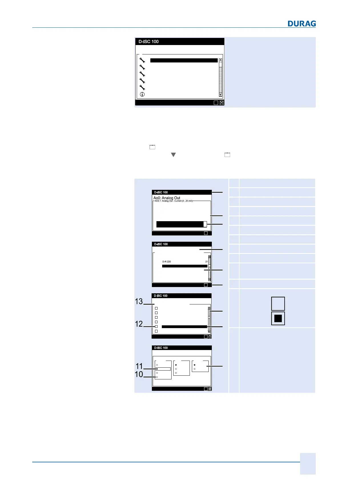
Definition of terms
in the display area
01.04.2013 12:37
Status: S1.1:Normal measurement
4.7433
mA
0.0000 2.500 5.0000
Menu: 4.2.1.S3
Status: S1.3:Normal measurement
Add / remove sensor
\\Channel setup\Sensor (S)\Add / remove sensor
D-FL 220 22
S1
S2
S3
S4
S5
S6
not assigned
not assigned
not assigned
not assigned
Menu: 3.3.1
Status: S1.3:Normal measurement
Communication parameter
Baudrate Parity
9600
19200
38400
None
Even
Stop Bits
1 Bit
2 Bits
Odd
57600
Menu: 4.2.S1.1.2.1
Info: Filter Off
S1:Channel 1 Status (S1.1)
\\...\Status\Channel 1\Status (S1.1)
Fault (F)
Maintenance / check function (C)
Message in: simple errors
Message in: critical errors
Message in: warnings
Message in: informations
1
4
2
3
5
6
7
8
9
drw_disc100_Definition der Displaybereiche_0002
E
E
E
E
1
Header
2
Display area
3
Bar graph
4
Window title
5
Menu range
6
Status line
7
Scroll bar
8
Current selection
9
Selection box
10
Radio button
(not selected)
11
Radio button (selected)
12
Checkbox
deactivated
activated
13
In the display:Channel name
for a menu:Menu path:
Table5.4: Term definitions
 Loading...