5 | Basic operation of the D-ISC 100
D-ISC 100 x xx2
75
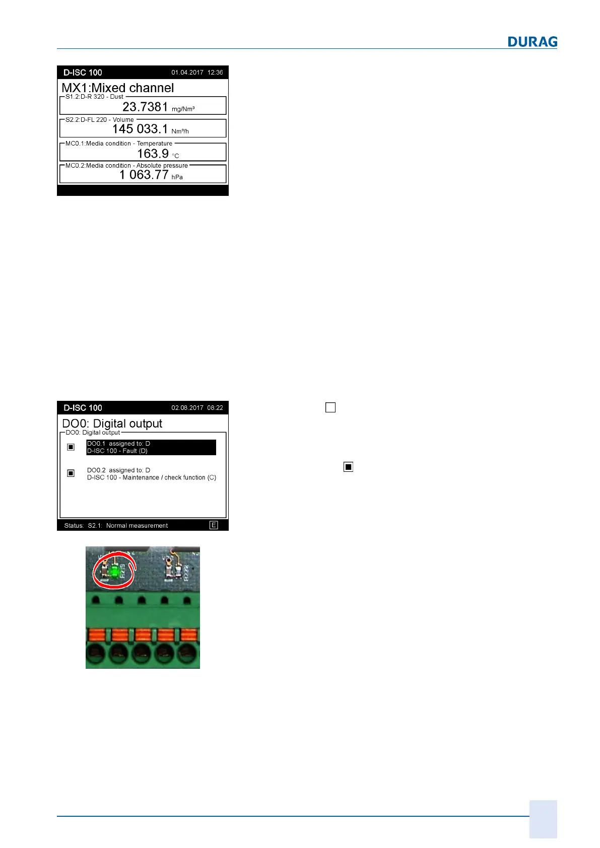
Fig.5.11: Measurement display MXo
Measurement display (Sn)
● Display of the measured values selected for the respective
sensor, together with the respective unit.
Measurement display (SXp)
● Displays the measured values selected for the respective ex-
ternal device, together with the respective unit
Measurement display (MC0)
● Displays the recorded media conditions with the respective
unit
Measurement display (AOm,
AIm)
● Displays the analogue output and input values
(current in mA)
Status display
(DOm, DIm)
The status of the individual inputs or outputs is displayed in the
status display for the digital in/digital out modules.
Fig.5.12: Status display DO0
Checkbox empty
= not active:
● Digital out module: there is voltage at the relay coil (relay en-
ergised).
● Digital in modul: There is voltage at the input.
Checkbox completed
= active:
● Digital out module: there is no voltage at the relay coil (relay
de-energised).
● Digital in modul: There is no voltage at the input.
Fig.5.13: Relay LED
The statuses of the inputs and outputs are also signalled by
LEDs near to the the connecting terminals (see figure on the
left).
e.g. DO0.1: Checkbox active -> there is voltage at the relay coil -
> LED on the terminal lights up.
The signals can be inverted in the D‑ISC100. See also Section
15.11.1 Example: Signal inversion setup (digital outputs) [}185].
Status display (NEm/NSm)
Status display for network modules.
● Check box "On-line" indicates active communication with this
module
● Check box "Rx" is active when data are being received
● Check box "Tx" is active when data are being sent
● Check box "Error" is active when defective packets are detec-
ted
 Loading...