MGR10 A/B/C - Revision : I (for 7.0 software revision) 42
SECTION 5 : MEASURING WITH THE MGR10
5.1 Connecting to the MGR10
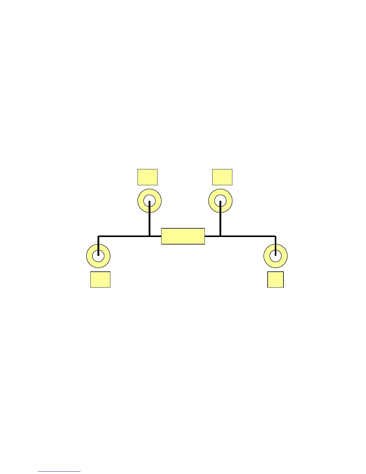
The MGR10 uses a four terminal method of measurement which eliminates errors due to lead
resistance. The measuring leads plug into the four front panel safety sockets. The sockets are
marked +U, -U, +I, & -I. Connections to the resistance to be measured should be as per Figure
5.1.1
Figure 5.1.1 Connection diagram
NOTE it is important to connect the I (current) leads outside the U (potential) leads
Rx
+U -U
+I -I
 Loading...