MGR10 A/B/C - Revision : I (for 7.0 software revision) 93
APPENDIX II : RS-232 Pin Connections
1 DCD Data Carrier Detect (not connected)
2 RXD Received Data (input)
3 TXD Transmitted Data (output)
4 DTR Data Terminal Ready (not connected)
5 GND Signal Ground
6 DSR Data Set Ready (not connected)
7 RTS Request To Send (output)
8 CTS Clear To Send (input)
9 RI Ring Indicator (not connected)
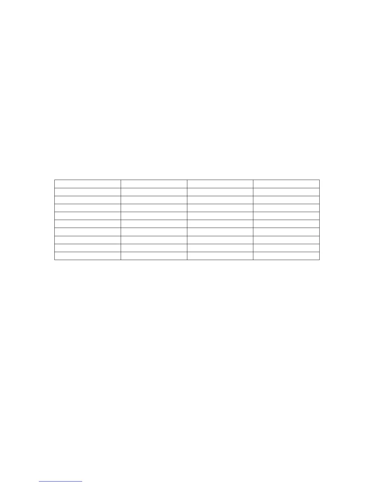
PC – 25 pin female PC – 9 pin female MGR10 – 9 pin male
8 1 Not used 1
3 2 Connected to 3
2 3 Connected to 2
20 4 Not used 4
7 5 Connected to 5
6 6 Not used 6
4 7 Connected to 8
5 8 Connected to 7
22 9 Not used 9
NOTA : some program may require to have the pin1 PC side connected to pin4 PC side and to pin 6
PC side .
 Loading...