04/10 MN04020001Z-EN
Parameter menu (PAR)
103
When P5.1 (2.3) = 25, you can set the digital output or a
signalling relay for the FBV.
The FBV actual value message enables the PID controller of the M-
Max
TM
to implement a direct “two-stage control”, as is commonly
used for HVAC applications.
Example: ventilation system with two fans (frequency inverter).
Under normal operating conditions, the maximum output power
of fan 1 (M1) is sufficient to maintain the actual value (PV) at the
reference value. When fan 1 is fully utilized and additional airflow
is required, a second fan (M2) with constant power is a simple
solution.
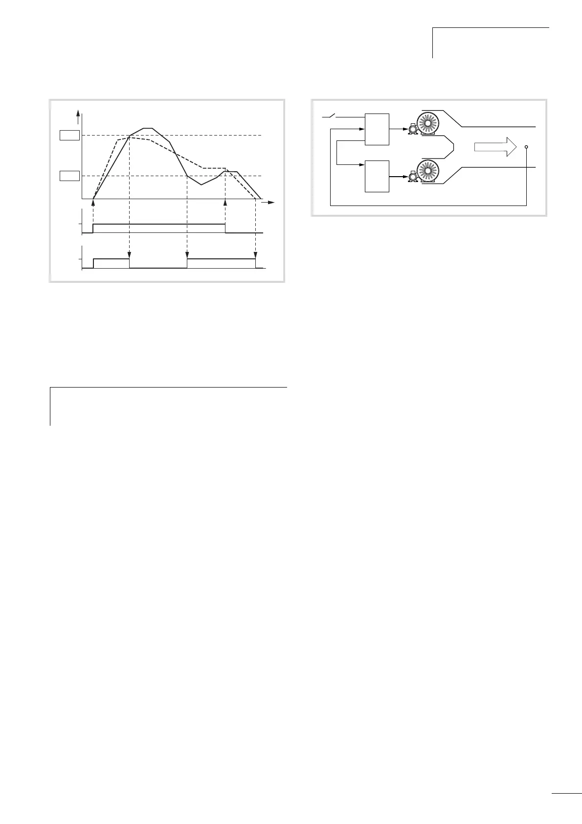
With the closed-loop control example shown here, the sequence is
based on the signal diagram in Fig. 90 The process variables in the
limit values are shown in percent (%). The output frequency (Hz)
is shown superimposed in the same diagram.
• Start of fan motor M1 with FWD signal. The actual value (PV) is
below the limit value of P9.16. The FBV output (P5.1 (23 = 25))
then switches and fan motor M2 (Start) starts automatically.
• The actual value rises and reaches the upper limit (P9.15). The
FBV output is automatically switched off (= fan M2 Off).
Fan M1 remains in operation and works in linear control mode.
In a correctly set up system, this is the normal operating range.
• If the actual value drops below the limit value (P9.16), the FBV
output is switched. and fan M2 is activated again to support fan
M1.
• When the FWD signal is removed from frequency inverter 1, the
inverter goes from RUN to STOP mode and decelerates the drive
over the set ramp time.
• When frequency inverter 1 is stopped, the FBV output is
automatically de-energized so that fan M2 also stops.
Figure 90: PID controller, actual value message FBV
a Output frequency [Hz].
b Actual value (process variable PV).
FWD: Start signal, clockwise rotating field.
FBV: Actual value message, limit values exceeded (P9.15,
P9.16).
h
The upper and lower actual value limits (P9.15, P9.16) are
“process messages”. They cannot be used for monitoring
the actual value signal. FBV is not a fault message.
Figure 91: Block diagram, ventilation with “two-stage control”
1: Frequency inverter with PID controller for fan motor M1.
2: Motor starter (frequency inverter, soft starter, contactor) for
fan motor M2.
FWD: Start signal drive 1.
FBV: Actual value message of drive 1 for activating drive 2.
PV: Process variable (air volume m
3
/h) as normalized actual
value.
Start: Start signal, drive 2.
PV
1
2
FWD
M2
M1
FBV
Start
0... 10 V/ 4... 20 mA
 Loading...


