Parameters
04/10 MN04020001Z-EN
130
Operational data indicator (MON)
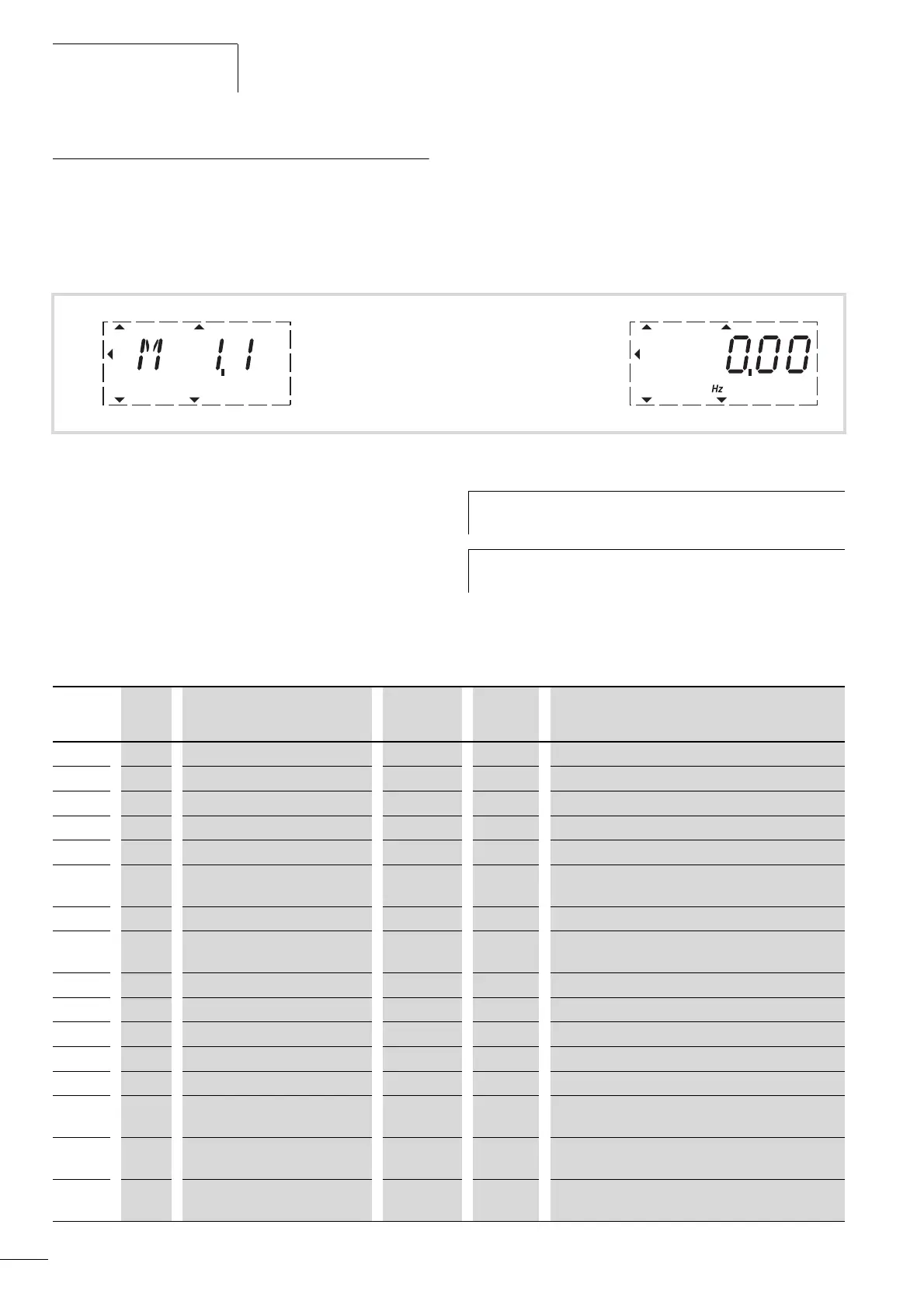
By applying the specified supply voltage (L1, L2/N, L3), the LCD
display is illuminated (= Power ON) and all segments are shown
briefly. The parameter number (M1.1) and the respective display
value (0.00) are then displayed automatically in alternating
sequence.
You can use the MON (Monitor) menu level to select the desired
operational data indicator (parameter number M…) with the
arrow buttons Í and Ú. The parameter number and the display
value are shown in alternation automatically, and the display can
be fixed on the selected display value with the OK button. If you
wish to access a different operational data indicator, press the OK
button once again. You can then make the selection with the
arrow buttons Í and Ú and confirm with the OK button. The
appropriate unit is shown under the respective operational data
indicator.
m
Display in automatic alternation l
Figure 105: Operational data indicator
RUN STOP ALARM FAULTREADY
REF
FWD REV I/O KEYPAD BUS
MON
PAR
FLT
RUN STOP ALARM FAULTREADY
REF
FWD REV I/O KEYPAD BUS
MON
PAR
FLT
h
The values of the operating data display cannot be
changed by hand (i. e. by value entry).
h
You can select operational data indicators during
operation (RUN).
PNU ID Designation Display
value
Unit Description
M1.1 1 Output frequency 0.00 Hz Frequency to motor
M1.2 25 Frequency reference value 0.00 Hz Frequency reference value
M1.3 2 Motor shaft speed 0 rpm Calculated speed of the motor (rpm)
1)
M1.4 3 Motor current 0.00 A Measured motor current
M1.5
4 Motor torque 0.0 % Calculated ratio of torque to rated torque of the motor
1)
.
M1.6 5 Motor power 0.0 % Calculated ratio of actual output power to rated motor
output
1)
.
M1.7
6 Motor voltage 0.0 V Measured output voltage to motor.
M1.8
7 Intermediate circuit DC voltage 000 V Measured intermediate circuit voltage
(depending on the supply voltage).
M1.9 8 Unit temperature 00 °C Measured heat sink temperature.
M1.10 9 Motor temperature 0 % % (calculated value)
M1.11 13 Analog input 1 0.0 % Value on AI1
M1.12 14 Analog input 2 0.0 % Value on AI2
M1.13
26 Analog output 1 0.0 % Value on AO1
M1.14 15 Digital input 0 - Status DI1, DI2, DI3 (see “Example of status displays“,
page 131).
M1.15
16 Digital input 0 - Status DI4, DI5, DI6 (see “Example of status displays“,
page 131)
M1.16
17 Digital output 1 - Status RO1, RO2, DO (see “Example of status displays“,
page 131).
 Loading...


