04/10 MN04020001Z-EN
Operational data indicator
(MON)
131
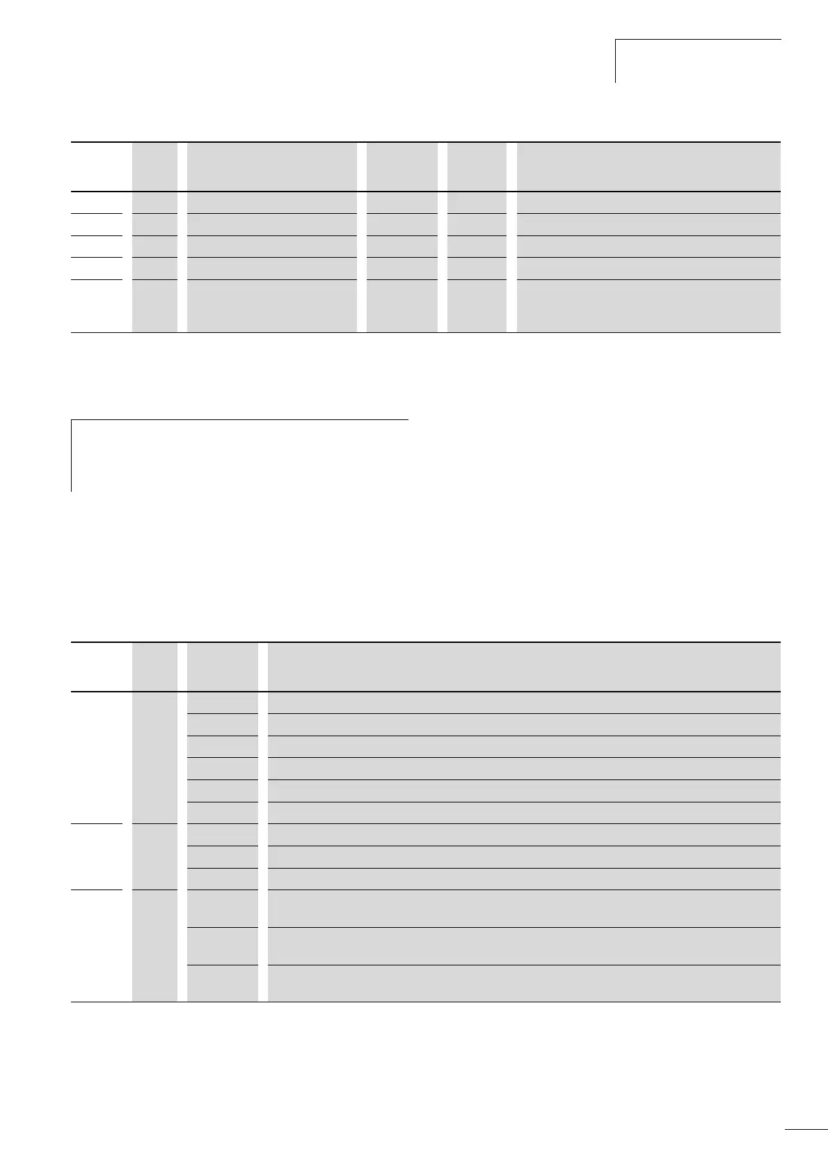
Example of status displays
The status displays of the digital inputs and outputs are
equivalent. These make it possible to check for whether an output
control signal (e.g. from an external controller) of the inputs (DI1
to DI6) activates the frequency inverter. This provides you with a
simple means for checking the wiring (wire breakage).
The following table shows a few examples.
Display value:
• 1 = activated = High
• 0 = not activated = Low
M1.17 20 PID setpoint 0.0 % Percentage of maximum setpoint.
M1.18 21 PID feedback 0.0 % Percentage of maximum actual value.
M1.19 22 PID error value 0.0 % Percentage of maximum fault value.
M1.20 23 PID output 0.0 % Percentage of maximum output value.
M1.21 1480 Counter, digital input 0 - Number of actuations of a digital input (DI1 - DI6)
assigned at P3.23. The reset command for the counter is
set at P3.24.
1) The calculated motor data (M1.3, M1.5 and M1.6) is based on the values entered in parameter group P7
(a section “Motor (P7)”, page 94
).
2) The calculated motor temperature (M1.10) considers the temperature model of the protection function in parameter group P8
(a section “Protective functions (P8)”, page 95)
h
Under the system parameters S3.1 to S4.1 (see Section
“System parameter”, page 128) you can also display the
operational data of the M-Max
TM
frequency inverter and
adjust the contrast of the display unit.
PNU ID Designation Display
value
Unit Description
PNU ID Display
value
Description
M1.14 15 0 No digital input (DI1, DI2, DI3) is actuated.
1 Control signal terminal 10 is actuated (DI3).
10 Control signal terminal 9 is actuated (DI2).
100 Control signal terminal 8 is actuated (DI1).
101 The control signal terminals 10 and 8 are actuated (DI3 + DI1).
111 The control signal terminals 10 and 9 and 8 are actuated (DI3 + DI2 + DI1).
M1.15 16 1 Control signal terminal 14 is actuated (DI14).
10 Control signal terminal 15 is actuated (DI15).
100 Control signal terminal 16 is actuated (DI16).
M1.16 17 1 Transistor DO is actuated. The transistor switches the voltage connected at control signal terminal 20 (DO+)
to control signal terminal 13 (DO-).
10 Relay RO2 is actuated.
The control signal terminals 25 (R21) and 26 (R24) are connected (closed changeover contact).
100 Relay RO1 is actuated.
N/O contact, control signal terminal 22 (R13) and 23 (R14) is closed.
 Loading...


