04/10 MN04020001Z-EN
31
3 Installation
Introduction
This chapter provides a description of the installation and the
electrical connections for the frequency inverter M-Max
TM
series.
Installation instructions
The instructions for installation in this manual apply for frequency
inverters of the M-Max
TM
series under protection type IP20.
In order to meet the requirements in accordance with NEMA 1
(IP21), you must, depending on the size of the housing, use the
optional housing accessories MMX-IP21-FS1, MMX-IP21-FS2 or
MMX-IP21-FS3.
The required installation instructions are shown in the setup
instructions AWA8230-2417.
Mounting position
The vertical mounting position may be tilted by up to 90° degrees.
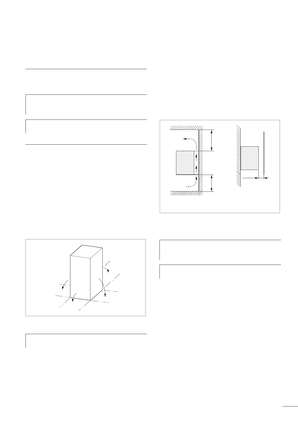
Cooling measures
In order to guarantee sufficient air circulation (thermal), free space
of at least 100 mm above the frequency inverter M-Max
TM
and at
least 50 mm under the frequency inverter is required.
The required cooling airflow is 10 m
3
/h for sizes FS1 and FS2 and
30 m
3
/h for size FS3 (refer to Section “Dimensions and frame size”
in the appendix on page 151).
The space in front should not be under 15 mm.
h
While installing and/or assembling the frequency inverter,
cover all ventilation slots in order to ensure that no
foreign bodies can enter the device.
h
Perform all installation work with the specified tools and
without the use of excessive force.
Figure 17: Mounting position
h
An installation that is turned by 180° (stood on its head)
is not permitted.
l
FS1, FS2: 10 m
3
/h; FS3: 30 m
3
/h
Figure 18: Space for air-cooling
h
Please note that the installation makes it possible to open
and close the control signal terminal covers without any
problems.
h
The frequency inverters of the M-Max
TM
series are
air-cooled with an internal fan.
 Loading...


