04/10 MN04020001Z-EN
63
5 Error and Warning Messages
Introduction
M-Max
TM
frequency inverters have several internal monitoring
functions. When deviations from the correct operating status are
detected, faults (FAULT) and warning messages (ALARM) are
differentiated between.
Error messages
Faults can cause faulty functionality and technical defects. The
inverter (frequency inverter output) is automatically disabled if a
fault is detected. After this, the connected motor comes to a stop
freely.
Error messages are shown on the display with an arrowhead
D
under FAULT and with the error code F… (F1 = last fault, F2 = last
but one fault, etc.).
Acknowledge fault message (Reset)
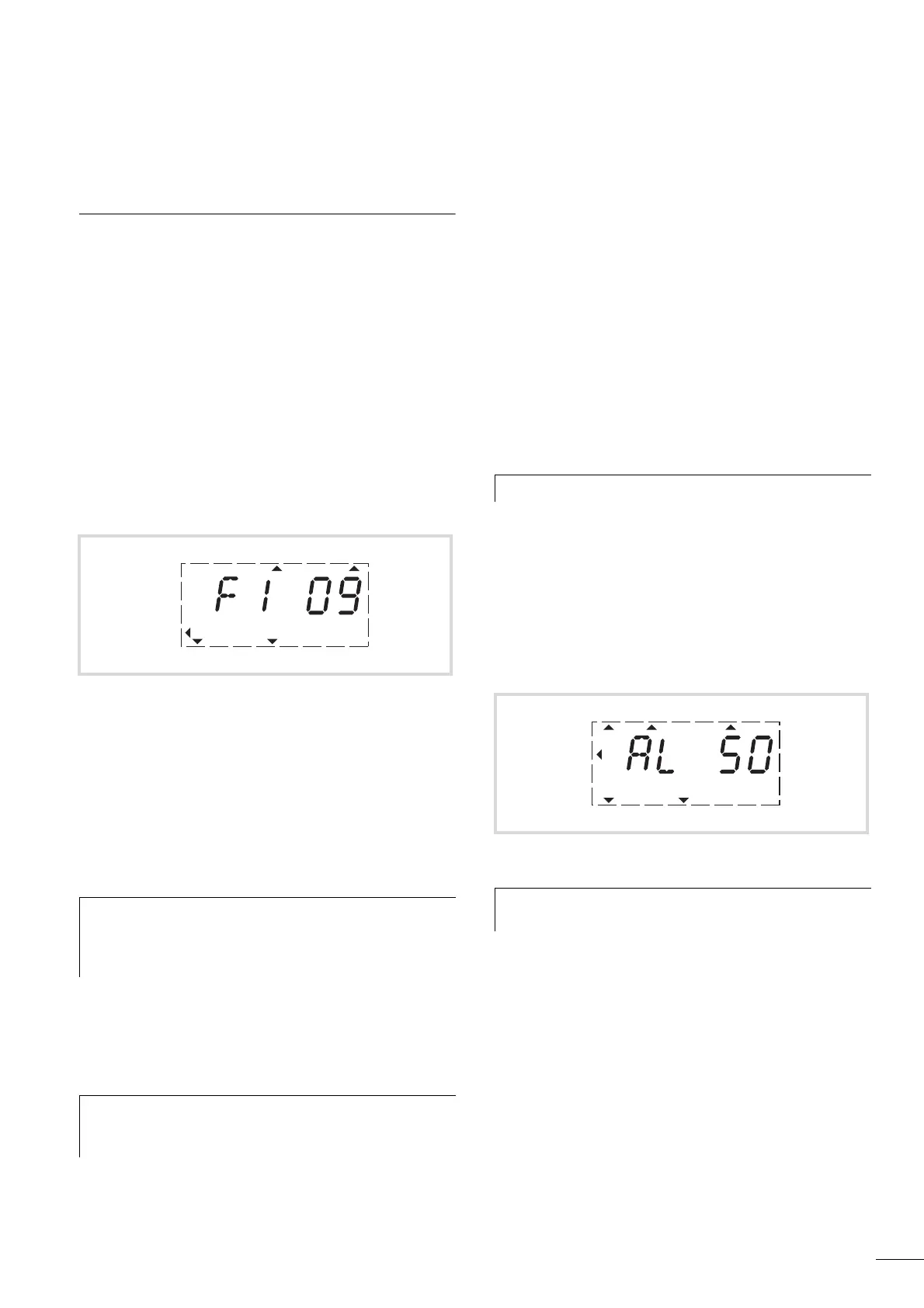
The current error message flashes (e.g. F1 09). It can be acknowl-
edged by pressing the BACK/RESET button or by actuating DI5
(default settings control signal terminal 15). The displayed error
then automatically stops flashing, the four horizontal bars (Reset)
are shown and the error message is then displayed continuously.
The arrow point
D underneath FAULT disappears.
The current fault message indication (F1...) is cleared when the
supply voltage is interrupted or when you press the BACK/RESET
key and then the OK key (indication d...) and then the BACK/RESET
key again. The indication goes out and the arrow tip Y flashes at
menu level MON.
Fault log (FLT)
The last nine faults can be called up and shown in succession in
the fault log (FLT).
For this select the FLT menu level (Y). Use the arrow buttons
Í
and Ú to call the faults F1 - F9 individually. Every error
message is stored with the time of the error occurrence under
d (day), H (hour) and m (minute). The call is made with the OK
button, and the selection with Í
and Ú arrow buttons.
The content of the error memory is cleared when the factory
setting is activated, when you press the BACK/RESET button, the
display of the menu level (Y) flashes and the STOP button is held
down for around 5 seconds.
Alarm messages
A warning message gives warning of possible damage and
indicates impending errors that can still be prevented, such as an
excessively high temperature rise.
Warning messages appear on the display with an arrow
D under
ALARM and AL with the respective code number. The code
numbers for faults and warning messages are identical.
In the given example (AL 50 = current setpoint signal 4–20 mA
interrupted), the drive stops following the absence of a reference
value. If no more measures are introduced because of the warning
message (e. g. a shutdown), the drive can start again
automatically in the example AL 50 when the current signal
returns (e.g. a contact fault in the signal line).
The alarm message (AL) is displayed alternating with the active
operational display value.
table 5 shows the error codes, their possible causes and indicates
correction measures.
Figure 61: Example of an error message (undervoltage)
j
Danger!
If a start signal is present, the drive is restarted automat-
ically, if P3.1 = 0 is set (REAF = Restart after FAULT) and
the error message has been acknowledged (Reset).
h
In the error register (display F…) it is only possible to
return to the menu level (arrow point Y FLT flashes) from
display d… .
RUN STOP ALARM FAULTREADY
REF
FWD REV I/O KEYPAD BUS
MON
PAR
FLT
h
Activating the factory settings will reset all parameters!
Figure 62: Example of an alarm message
h
If a warning message occurs, the frequency inverter
remains active (READY, RUN).
RUN STOP ALARM FAULTREADY
REF
FWD REV I/O KEYPAD BUS
MON
PAR
FLT
 Loading...


