Parameters
04/10 MN04020001Z-EN
100
PID controller (P9)
The frequency inverters of the M-Max
TM
series are provided with
a PID controller that you activate with P9.1 = 1. The controller can
be deactivated via a digital input (DI6 in FS) P3.12 = 6.
h
PID control is superimposed on the frequency inverter
function. You should therefore set all of the frequency
inverter’s drive-related parameters, such as maximum
output frequency (motor speed), acceleration and
deceleration ramps (mechanical load, belts). Frequency
inverter and motor are process-integrated actuators. The
output frequency to the motor (which determines the
speed) is specified as manipulated variable from the PID
controller.
h
When the PID controller is activated, the setpoints and
actual values become process variables and are
normalized automatically into percentages (%). For
example, the specified setpoint (0 - 100 %) here is the
same as a volume flow (0 - 50 m3/h). The actual value
here is the volume flow (m3/h) from a suitable sensor,
which is evaluated again as a percentage (0 - 100 %).
If this process data is to be displayed in the physical
variable (m
3
/h), you can set the conversion with
parameter P9.19 (a “Display factor (P9.19)”).
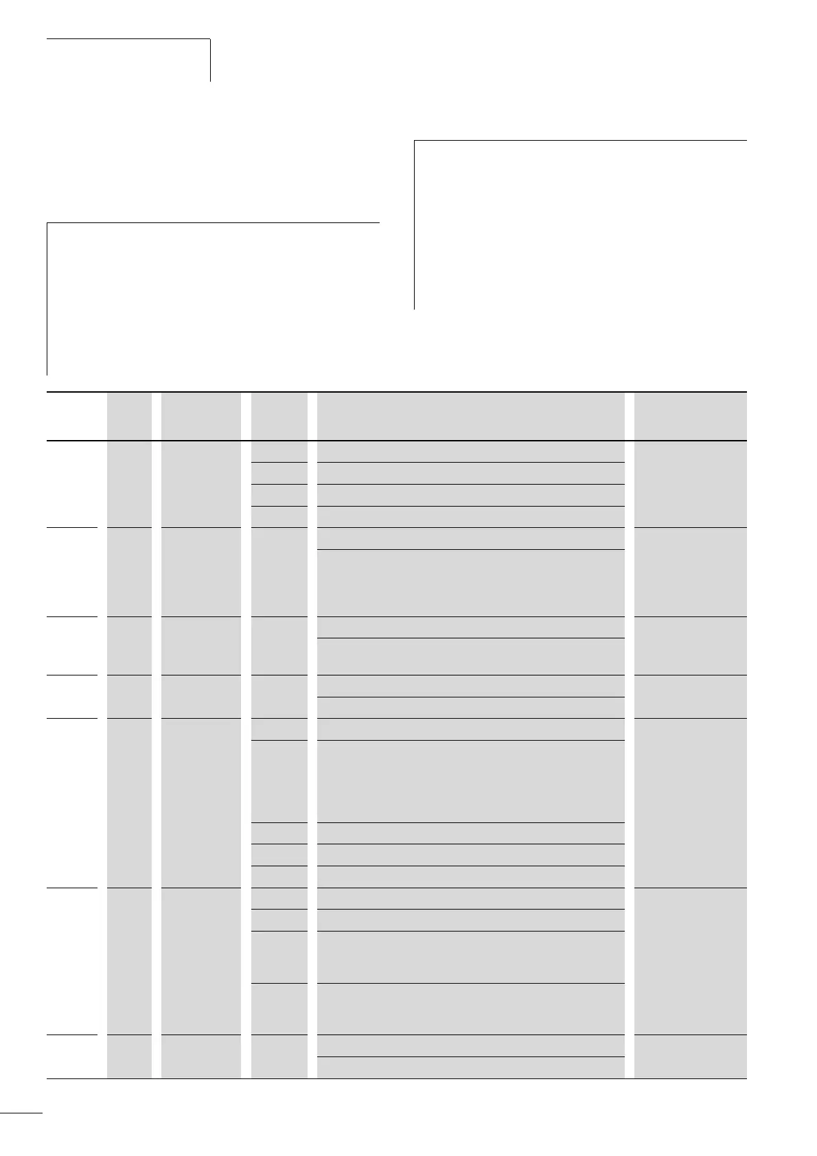
PNU ID Access right
RUN
Value Description Factory setting
(P1.3)
P9.1 163 / PID Controller 0
0 Deactivated
1 Activated for drive control.
2 Activated for external application.
P9.2 118 / PID controllers, P amplification 100
Setting range: 0.0 - 1000 %
Proportional Gain (KP)
• Low values attenuate the control action.
• High values can cause oscillation.
P9.3 119 / PID controller, I reset time 10.0
Setting range: 0.00 - 320.0 s
Integral time constant
P9.4 167 / PID controller, setpoint input via operating unit 0.0
Setting range: 0.0 - 100.0 %
P9.5 332 / PI controller, setpoint source 0
0 The setting range is limited by P6.3 (raised starting frequency) and
P6.4 (end frequency).
• Potentiometer (keypad)
• Frequency [Hz]
• Process variable [%] with P9.1 = 1
1 Fieldbus
2 AI1
3 AI2
P9.6 334 / PID controller, actual value (PV) 2
0 Fieldbus
1 AI1 and S2, (a figure 39, page 43)
P2.1=0 (0mA/0V)
P2.1=1 (4mA/2V)
2 AI2 and S3, (a figure 39, page 43)
P2.5=0 (0mA/0V)
P2.5=1 (4mA/2V)
P9.7 336 / PID controller, actual value limiting, minimum 0.0
Setting range: 0.0 - 100.0 %
 Loading...


