04/10 MN04020001Z-EN
Electrical Installation
43
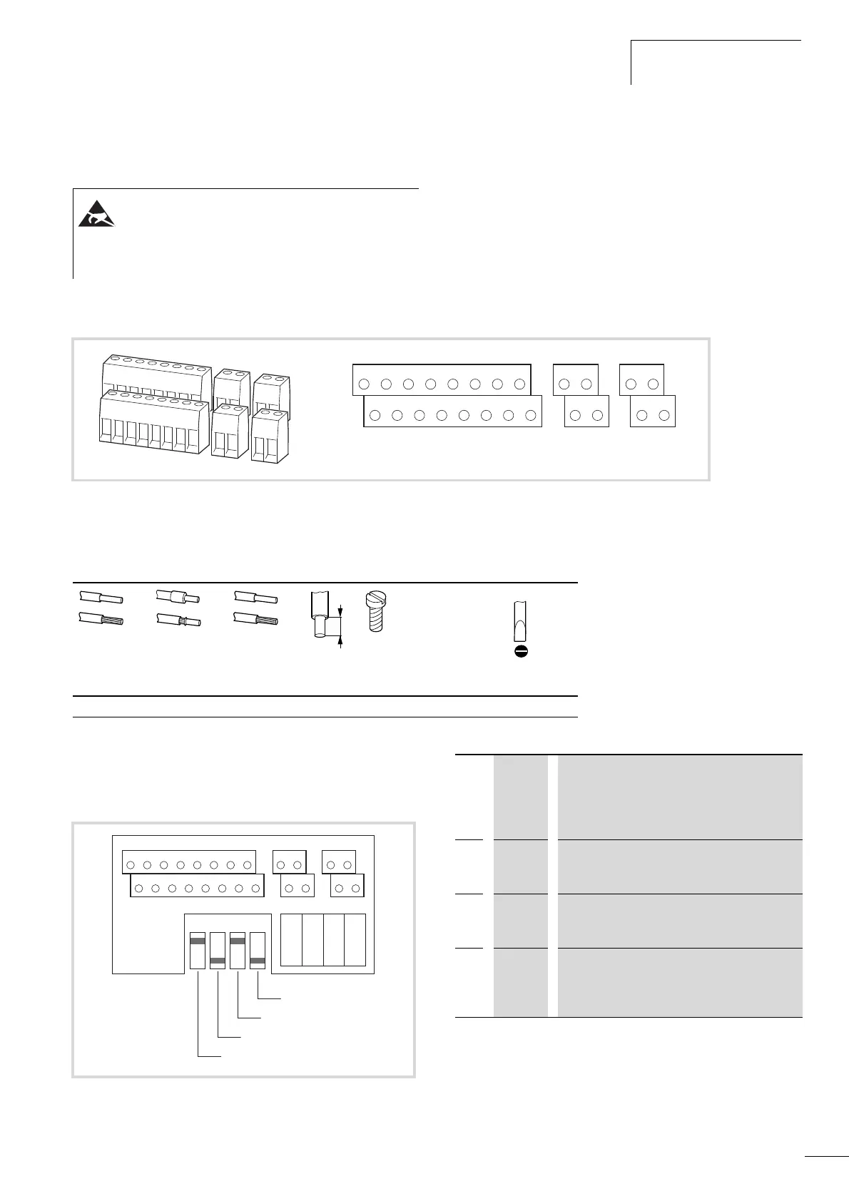
Arrangement and connection of the control signal
terminals
The following figure shows the arrangement and designation of
the control signal terminals of the M-Max
TM
.
Table 3: Possible sizes and specifications of the connection lines on the
control signal terminals
Microswitches and control signal terminals
Four microswitches are arranged under the cover plate. These are
used to configure the control signal terminals directly.
ESD measures
Discharge yourself on a grounded surface before touching
the control signal terminals and the controller PCB. This
protects the device from destruction by electrostatic
discharge.
Figure 38: Assignments and designations for control signal terminals
12367
8
9
10 25 24
4 5 13 14 15 16 18 20 22 23 26
AI2
DO-GND
DI4 DI5 DI6 AO DO+
R13
R14 - R24
+
10V AI1 GND
24V
DI-C
DI1 DI2 DI3 A B R21 R22
M3
mm
2
mm
2
AWG mm Nm ft-lbs mm
0.14 - 1.5 0.25 - 0.5 26 - 16 5 0.22 - 0.25 0.16 - 0.18 0.4 x 2.5
Figure 39: Microswitch factory settings
12367
8
9
10 25 24
4 5 13 14 15 16 18 20 22 23 26
AI2
DO-GND
DI4 DI5 DI6 AO DO+
R13
R14 - R24
+
10V AI1 GND
24V
DI-C
DI1 DI2 DI3 A B R21 R22
LOGIC
- +
AI 1
V mA
AI 2
V mA
RS 485
- term.
S4 = RS485 (-)
S3 = AI2 (mA)
S1 = LOGIC (+)
S2 = AI1 (V)
S1 LOGIC Control logic:
+ = positive logic (FS)
Source type
- = negative logic
Sink type
S2
AI1 Analog input 1 (P2.1):
V = 0 - +10 V (FS)
mA = 4 - 20 mA
S3
AI2 Analog input 2 (P2.5):
mA = 4 - 20 mA (FS)
V = 0 - +10 V
S4 RS485 Bus terminating resistor (control signal terminal
A/B):
- = disconnected
term. = switched on (terminator)
 Loading...


