Engineering
04/10 MN04020001Z-EN
24
Electrical power network
Mains connection and configuration
The frequency inverters of the M-Max
TM
series can be connected
and operated with all control-point grounded AC power networks
(see IEC 60364 for more information in this regard).
The connection and operation of frequency inverters to
asymmetrically grounded TN networks (phase-grounded Delta
network "Grounded Delta", USA) or non-grounded or high-
resistance grounded (over 30 O) IT networks is only conditionally
permissible.
If the M-Max
TM
frequency inverters are connected to an
asymmetrically grounded network or to an IT network (non
grounded, insulated), the internal interference suppression filter
must be disconnected (unscrew the screw marked EMC,
a section “Electrical Installation”, page 37).
The required filtering for electromagnetic compatibility (EMC) is
then no longer present.
Mains voltage and frequency
The standardized mains voltages (IEC 60038, VDE017-1) for
energy suppliers (EVU) guarantee the following conditions at the
transition points:
• Deviation from the rated value of voltage:
maximum ±10 %
• Deviation in voltage phase balance: maximum ±3 %
• Deviation from rated value of the frequency:
maximum ±4 %
The broad tolerance band of the M-Max
TM
frequency inverter
considers the rated value for
European as (EU: U
LN
= 230 V/400 V, 50 Hz) and
American as (USA: U
LN
= 240 V/480 V, 60 Hz) standard voltages:
• 120 V, 50/60 Hz at MMX11
• 230 V, 50 Hz (EU) and 240 V, 60 Hz (USA) at MMX12 und
MMX32,
• 400 V, 50 Hz (EU) and 480 V, 60 Hz (USA) at MMX34…
For the bottom voltage value, the permitted voltage drop of 4 %
in the consumer circuits is also taken into account, therefore a
total of U
LN
- 14 %.
• 100 V device class (MMX11):
110 V -15 % - 120 V +10 % (94 V -0 % - 132 V +0 %)
• 200-V device class (MMX12, MMX32):
208 V - -15 % – 240 V + +10 % (177 V - 0 % – 264 V + 0 %)
• 400-V device class (MMX34):
380 V - -15 % – 480 V + +10 % (323 V - 0 % – 528 V + 0 %)
The permitted frequency range is 50/60 Hz here (45 Hz - 0 % – 66
Hz + 0 %).
Voltage balance
Because of the uneven loading on the conductor and with the
direct connection of greater power ratings, deviations from the
ideal voltage form and unsymmetrical voltages can be caused in
three-phase AC power networks. These asymmetric divergences in
the mains voltage can lead to different loading of the diodes in
mains rectifiers with three-phase supplied frequency inverters and
as a result, to an advance failure of this diode.
If this condition is not fulfilled, or symmetry at the connection
location is not known, the use of an assigned main choke is
recommended (see “Appendix“, Section “Mains chokes”,
page 169).
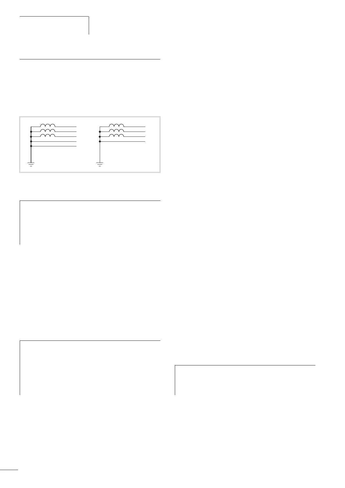
Figure 10: AC power networks with grounded center point (TN-/TT
networks)
h
While planning the project, consider a symmetrical
distribution to the three external conductors, if multiple
frequency inverters with single phase supplies are to be
connected. The total current of all single phase consumers
is not to cause an overload of the neutral conductor
(N-conductor).
h
Measures for electromagnetic compatibility are
mandatory in a drive system, to meet the legal
requirements for EMC- and low-voltage regulations.
Good grounding measures are a prerequisite for the
effective insert of further measures such as shielding or
filters here. Without respective grounding measures,
further steps are superfluous.
L2
PEN
L1
L3
h
In the project planning for the connection of three-phase
supplied frequency inverters (MMX32, MMX34), consider
only AC power networks that handle permitted
asymmetric divergences in the mains voltage F +3 %.
 Loading...


