Installation
04/10 MN04020001Z-EN
32
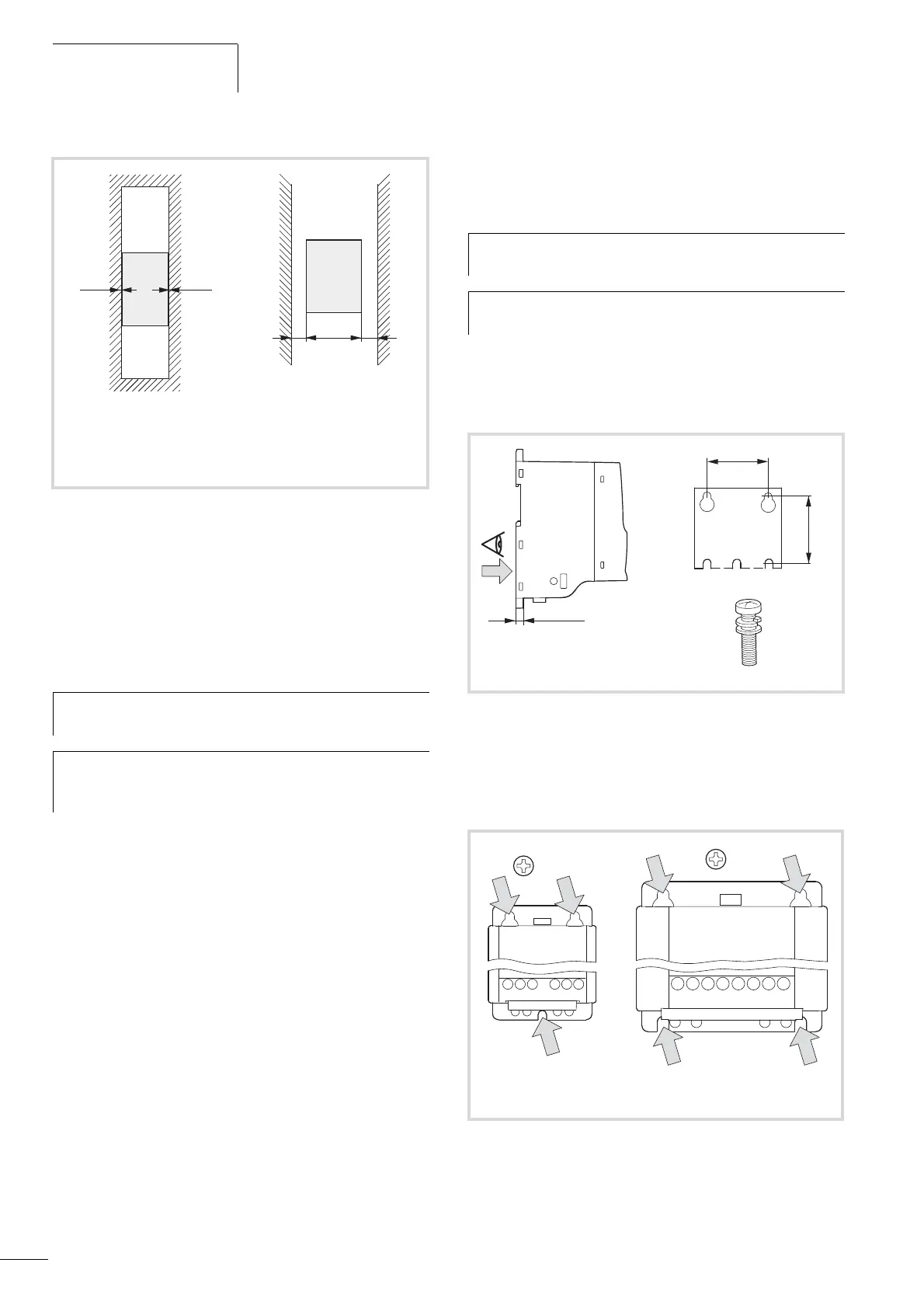
Up to an ambient temperature of +40 °C, a set-up height of up to
1000 m and a pulse frequency of up to 4 kHz, the frequency
inverters of the M-Max
TM
series do not require any space at the
sides.
Higher ambient temperatures (up to a maximum of +50 °C), pulse
frequencies f
PWM
(up to maximum 16 kHz) and set-up heights (up
to 2000 m) require space on the sides of at least 20 mm.
Fixing
You can mount an M-Max
TM
frequency inverter on screw mounts
or on a mounting rail.
Fastening with screws
The number and arrangement of required bore holes (mounting
dimensions a1 and b1 in figure 20) are also imprinted in the base
plate of the M-Max
TM
device.
Install the screws in the specified positions first. Then set the
frequency inverter on the prepared wall-mount and tighten all
screws. The permitted maximum tightening torque for the
fastening screws is 1.3 Nm.
i F 40 °C
f
PWM
F 4 kHz (P11.9)
i > 40 °C (max. 50 °C)
f
PWM
> 4 kHz (P11.9)
Figure 19: Free space at the sides
h
The pulse frequency (f
PWM
) can be adjusted with
parameter P11.9.
h
Devices with strong magnetic fields (e.g. inductors or
transformers) should not be installed in the immediate
vicinity of the M-Max
TM
device.
f 0 f 0
f 20
f 0.498”
h
Install the frequency inverter only on a nonflammable
mounting base (e.g., on a metal plate).
h
Dimensions and weights of the frequency inverter
M-Max
TM
are located in the appendix.
Figure 20: Mounting dimensions
1.3 Nm (11.5 lb-in) 1.3 Nm (11.5 lb-in)
Figure 21: Configuration for mounting with screws
b1
a1
= M4
= M5
 Loading...


