04/10 MN04020001Z-EN
Parameter menu (PAR)
83
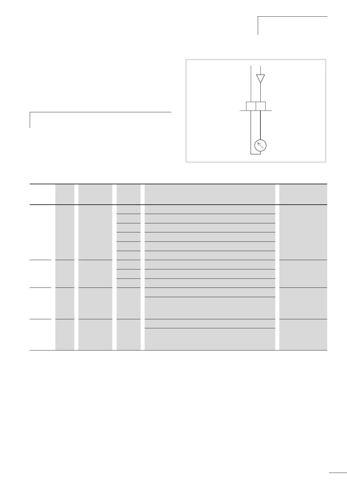
Analog output (P4)
An analog voltage signal from 0 - +10 V is output at control signal
terminal 18. The maximum permissible load is 10 mA. Reference
potential is GND on control signal terminals 3 and 5.
In the factory setting, the voltage signal (0 - 10 V) is proportional
to the output frequency f-Out = 0 - f
max
(P6.4).
h
The output signal is not monitored by the frequency
inverter.
Figure 76: Analog output AO
5
0...+10 V
AO
18
GND
< 10 mA
f-Out
-
+
PNU ID Access right
RUN
Value Description Factory setting
(P1.3)
P4.1 307 / AO signal (Analog Output). 1
0 Deactivated
1 Output frequency f-Out = 0 – f
max
(P6.4)
2 Output current I
2
= 0 – I
N Motor
(P7.1)
3 Torque M
N
= 0 – 100 % (calculated value)
4 PID controller, output (0 - 100 %)
P4.2 310 / AO, minimum value 1
0 0V
1 2V (live-zero)
P4.3 1456 / AO, gain 100.00
Gain Factor: 0.00 - 200.00 %.
The maximum value set here always corresponds to the maximum
output voltage 10 V.
P4.4 1477 / AO, filter time constant 0.10
0.01 - 10.00 s = Filter time constant for the analog output
voltage.
a section “Filter time constant”, page 77
 Loading...


