Parameters
04/10 MN04020001Z-EN
82
Example A: P3.1 = 1 (P6.8 = 0)
The start enable via control signal terminal 8 (DI1) is always
required for operation:
• Actuation control signal terminal 8 (DI1) = Start enable,
clockwise rotating field (FWD).
• Actuation control signal terminal 8 (DI1) plus control signal
terminal 9 (DI2) = Start enable anticlockwise rotating field
(REV).
The separate actuation of control signal terminal 9 (DI2) does not
allow any start enable.
Example B: P3.1 = 2
Standard actuation for a drive with pushbutton switch (Normally
open, Normally closed) and self-actuating.
Parameter P3.1 = 2 enables this actuation via the control signal
terminals 8 (DI1) and 9 (DI2) to be simulated.
Parameter P3.4 = 3 enables the rotation reversal (FWD
n REV) to
be activated (reversing starter) via control signal terminal 10 (DI3).
a Set P3.9 = 0.
P3.31 1418 / DI1 logic (control signal terminal 8). 0
The logic activates the response of the control signal terminal
( a figure 73).
N/O contact (failsafe) N/C contact.
0 N/O contact.
1 N/C contact.
P3.32 1419 / DI2 logic (control signal terminal 9). 0
Function same as P3.31.
P3.33 1420 / DI3 logic (control signal terminal 10). 0
Function same as P3.31.
P3.34 1421 / DI4 logic (control signal terminal 14). 0
Function same as P3.31.
P3.35 1422 / DI5 logic (control signal terminal 15). 0
Function same as P3.31.
P3.36 1423 / DI6 logic (control signal terminal 16). 0
Function same as P3.31.
P3.37 1480 / Hand mode 0
Assignment of control signal terminal as per P3.2.
PNU ID Access right
RUN
Value Description Factory setting
(P1.3)
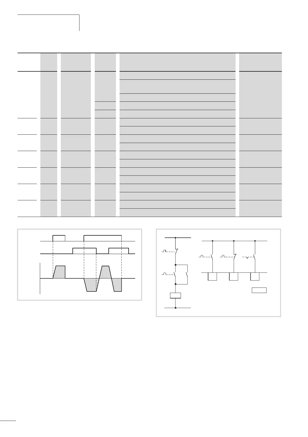
Figure 74: DI1 (FWD) + DI2 = REV
DI1 (FWD)
FWD
DI2 (REV)
REV
f
out
(Motor)
Figure 75: Example: Start stop impulse
DI1
RUN STOP
+ 24 V
8
DI2
9
P3.4 = 3
DI3
10
OFF = FWD
ON = REV
 Loading...


