04/10 MN04020001Z-EN
Parameter menu (PAR)
119
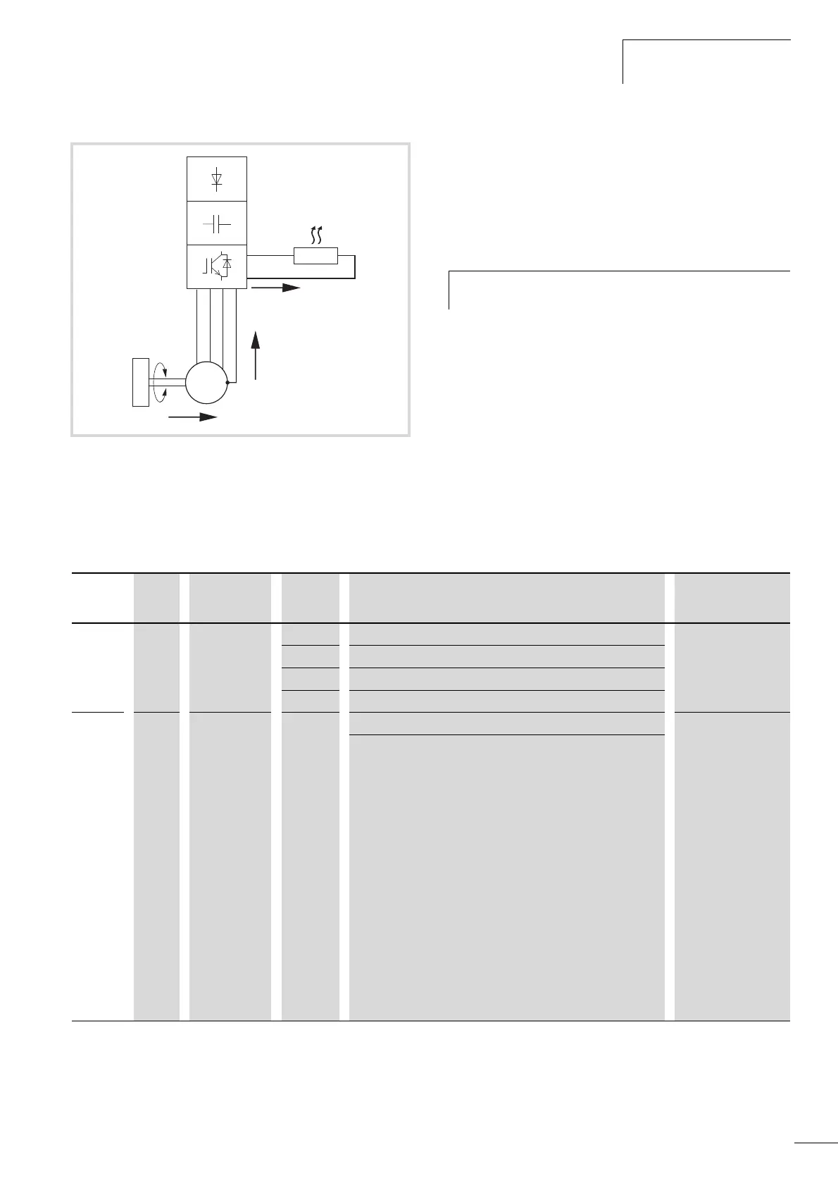
The brake chopper can be activated at parameter P12.5. This
function is only activated with the three-phase frequency inverters
MMX34…3D3… (3.3 A) to MMX34…014… (14 A). These
ratings have an internal brake transistor which can dissipate
excess brake energy via an external power resistor (connection
terminals R+ and R-) when large flywheel masses or short
deceleration times are involved.
Figure 101: Regenerative braking with external braking resistor
a Machine flywheel mass
b Inverter with brake chopper (brake transistor)
c Brake resistor (R
B
)
a Energy flow (brake torque)
h
This parameter is not visible with frequency inverters
without a braking transistor.
PNU ID Access right
RUN
Value Description Factory setting
(P1.3)
P12.5 504 - Brake chopper 0
0 Brake-chopper deactivated
1 Automatic activation in operation (RUN)
2 Automatic activation in operation (RUN) and upon stop (STOP)
P12.6 1447 - Brake chopper, switching threshold 765
This function is only active with the three-phase frequency
inverters MMX34…3D3… (3.3 A) to MMX34…014… (14 A).
Setting range: 0 - 870 V
The switching threshold for the brake transistor should always be
above the maximum DC link voltage.
For example, allowing for the maximum permissible mains voltage
peak of +10%:
U
LN
=400VAC
U
LN
+10%=400VAC=440VAC (
U
DC
= 1.35 x U
LNmax
= 1.35 x 440 V = 594 V DC (maximum
permissible DC link voltage in motor operation).
Allowing for an energy absorption from the DC link of around 30%
during braking, the on threshold here for the braking transistor
should be set to around 780 V.
Note: Lower values for the on threshold will switch on the braking
resistor earlier so that it is subject to a greater load.
The DC link voltage is shown at M1.8. In practice, the value of the
DC link voltage is around 565 V at U
LN
= 400 V.
 Loading...


