Operation
04/10 MN04020001Z-EN
58
The start release is done by actuating one of the digital inputs with
+24 V:
• Terminal 8: FWD = Clockwise rotating field (Forward Run)
• Terminal 9: REV = Counterclockwise rotating field (Reverse
Run)
The control commands are interlocked (exclusive OR) and require
a rising voltage edge.
The start release (FWD, REV) is shown in the top status line (LCD
display) by the arrow (
D) switching from STOP to RUN.
The frequency is shown with a minus sign with a start release with
a left rotating field (REV).
You can now set the output frequency (0 – 50 Hz) and therefore
the speed of the connected ac motor (0 – n
motor
) with the setpoint
value potentiometer via terminal 2 (proportional voltage signal
0 – +10 V). The change in output frequency here is delayed based
on the specified acceleration and deceleration ramps. In the
factory settings, these times are set to 3 seconds.
The acceleration and deceleration ramps specify the time change
for the output frequency: from zero to f
max
(FS = 50 Hz) or from
f
max
back to zero.
figure 59 on page 59 shows a good example of the process, if the
release signal (FWD/REV) is switched on and the maximum
setpoint voltage (+10 V) is applied. The speed of the motor follows
the output frequency depending on the load and moment of
inertia (slip), from zero to n
max
.
If the release signal (FWD, REV) is switched off during operation,
the inverter is blocked immediately (STOP). The motor comes to an
uncontrolled stop (see a in figure 59, page 59).
A controlled run-down can be set using parameter P6.8 (STOP
function) (P6.8 = 1).
The relevant deceleration time is set in parameter P6.6. The
acceleration time is set in parameter P6.5.
Information on settings and the description of the parameters used
here is provided in Section “Drives control (P6)”, page 88.
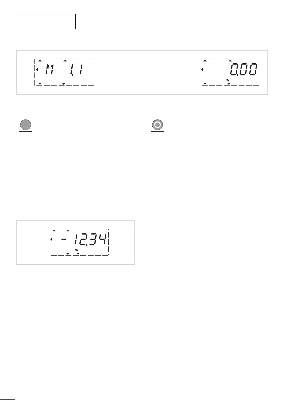
p Display in automatic alternation P
Figure 57: Operational data indicator (operational)
RUN STOP ALARM FAULTREADY
REF
FWD REV I/O KEYPAD BUS
MON
PAR
FLT
RUN STOP ALARM FAULTREADY
REF
FWD REV I/O KEYPAD BUS
MON
PAR
FLT
By actuating the OK button, you can set the display
mode to stay on the value for the output frequency
(0.00 Hz).
Figure 58: Operation (RUN) via control signal terminal (I/O) with left
rotating field (REV) (e.g. -12.34 Hz)
RUN STOP ALARM FAULTREADY
REF
FWD REV I/O KEYPAD BUS
MON
PAR
FLT
The stop command can also be given via the STOP
button on the operating unit. The STOP button is
active in all operating modes. It can be disabled with
parameter (P6.16 = 0).
 Loading...


