PROFIBUS-DPV0 functions
97
11/04 MN01219002Z-EN
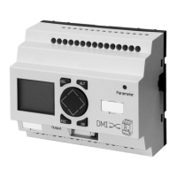
The inputs 1 to 3 of the DMI can be connected with switches
or pushbuttons to the local control of the motor to suit the
selected motor-starter function ( a section “Motor
starter”, Page 44).
Input 4 and 5 are intended for connection of the auxiliary
switch, in order to recognise the switching state of the
circuit-breaker.
Meaning of the data inputs
The read data inputs have the following meaning:
Table 12: Data content of module 3 data inputs
Designation
Meaning Precondition
Circuit-breaker
position
01
11
Normal operation of the circuit-
breaker (communication in order)
Circuit-breaker faulty or not
present (communication not
present)
–
Circuit-breaker
state
00
01
10
11
Initialisation running
Circuit-breaker is in the “OFF”
state
Circuit-breaker is in the “ON”
state
Circuit-breaker is in the
“Tripped” state
–
Delta
configuration
0
1
The motor will not be operated in
delta configuration
The motor is operated in delta
configuration
Outputs 0, 2, 3 have been
parameterized for “star-delta
starter” or
the outputs 0, 1, 2 and 3 have
been parameterized for “star-
delta-reversing starter”
General warning
Is set if a warning or a trip is present
from the circuit-breaker
–
Input 0 to 5 State of the digital inputs of the DMI. –
Load rejection
prewarning
At least one phase current has exceeded
the load warning limit (I
r
= 70 %)
–
Artisan Technology Group - Quality Instrumentation ... Guaranteed | (888) 88-SOURCE | www.artisantg.com

 Loading...


