Operating panel devices
2.40 EST2 System Operations Manual
Operating LED/switch modules
The front panel LED/switch modules provide manual control to
various portions of the system. The operator may view LEDs to
determine the status of a device, or press an associated switch
pad to change its state. During any change of state, the LEDs
flash through a duty cycle. All commands may be cancelled by
pressing the switch pad a second time before the command is
executed.
Reading front panel LEDs
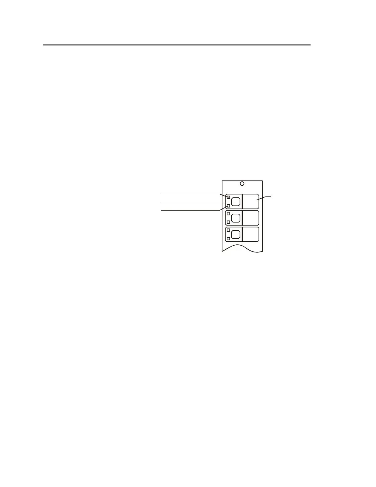
Each switch has two LEDs. A flashing sequence on the upper
LED indicates the activation or restoration of a device. The
lower LED operates independently, but it usually indicates the
status of a function related to the switch pad.
Upper LED
Function Label
STDOP035.CDR
Switch Pad
Lower LED
Figure 2-24: Front panel LED/switch module
Activating devices at the front panel
To activate a device, press its corresponding switch. The upper
LED will flash with a 10% duty cycle as shown in Figure 2-25
(top). During the 10% duty cycle, the LED is off more than it is
on. The LED stops flashing and remains lit when the device is
fully activated.
Restoring devices at the front panel
To restore a device, press its corresponding switch. The upper
LED will flash with a 90% duty cycle as shown in Figure 2-25
(bottom). During the 90% duty cycle, the LED is on more than it
is off. The LED turns off completely when the device is fully
restored.