minimum 700 MPa tensile strength and equally ght
ened in a cross‑paern in
3 ghtening stages to a nal torque of 30 Nm to make sure equal compression of
the O‑ring and clamping of the anges.
Tighten all inlet ange bolts again when the system is under vacuum. Make sure that
torques or other forces are not transmied to the pump from the vacuum system or the
related pipelines. If necessary, install an inlet vibraon damper between the pump inlet
and the vacuum system and install the base of the pump to a rigid support, as given in
Base mounng on page 42.
4.3.4 Base mounng
The base of the pump can be installed to a rigid support using the tapped xing holes.
Refer to Figure: nEXT 240 dimensions (mm), Figure: nEXT 300 dimensions (mm) and
Figure: nEXT 400 dimensions (mm) for the installaon hole details.
Note:
Remo
ve the four rubber feet from the four tapped xing holes before you base mount
the pump.
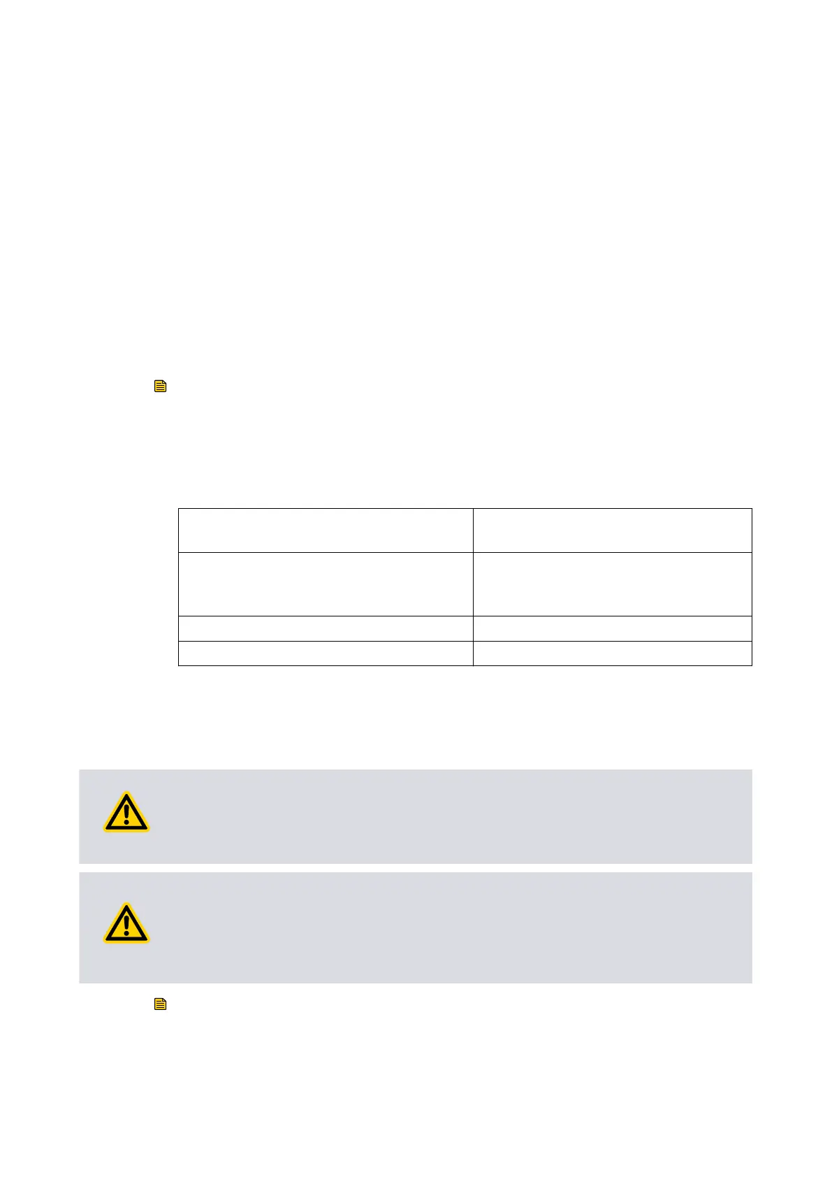
Obey the requirements that follows to make sure that the pump stay secured if the
pump seize:
Support must withstand a destrucve tor-
que of:
6 KNm
Installaon screws:
4quanty of M8 to ISO898‑1 strength
class 12.9 (nominal ten-
sile strength 1200 MPa)
Screw engagement length: 6 mm minimum
Fastening torque: 15 Nm (1.53 kgf.m)
Use this method for installaon if the pump supports the weight of the vacuum system.
Make sure that the weight of the vacuum system is not more than 20 kg.
4.3.5 Backing port connecon
WARNING: PUMP OVER‑PRESSURE
Risk of damag
e to equipment. To prevent over-pressure in the pump, do not limit the
exhaust line when you vent from a posive pressure gas supply.
CAUTION: BEARING LIFE
Risk of damage t
o equipment. Do not use the pump with a backing pressure less than
5 x 10
-4
mbar (5 x 10
-2
Pa). Lower backing pressures increases the evaporaon rate of
the lubricaon oil and can decrease the life of the bearings.
Note:
Make sure that the ducng is done at the backing line if oil mis
t or hazardous substances
are available.
04/2022 - ©Edwards Limited
Page 42B80000880_G
B80000880_G - Ins
t
allaon