RS232 interface. When the RS485
opon is selected, it is easy to connect number of
pumps to a single master. Refer to Figure: RS485 mul‐drop connecon.
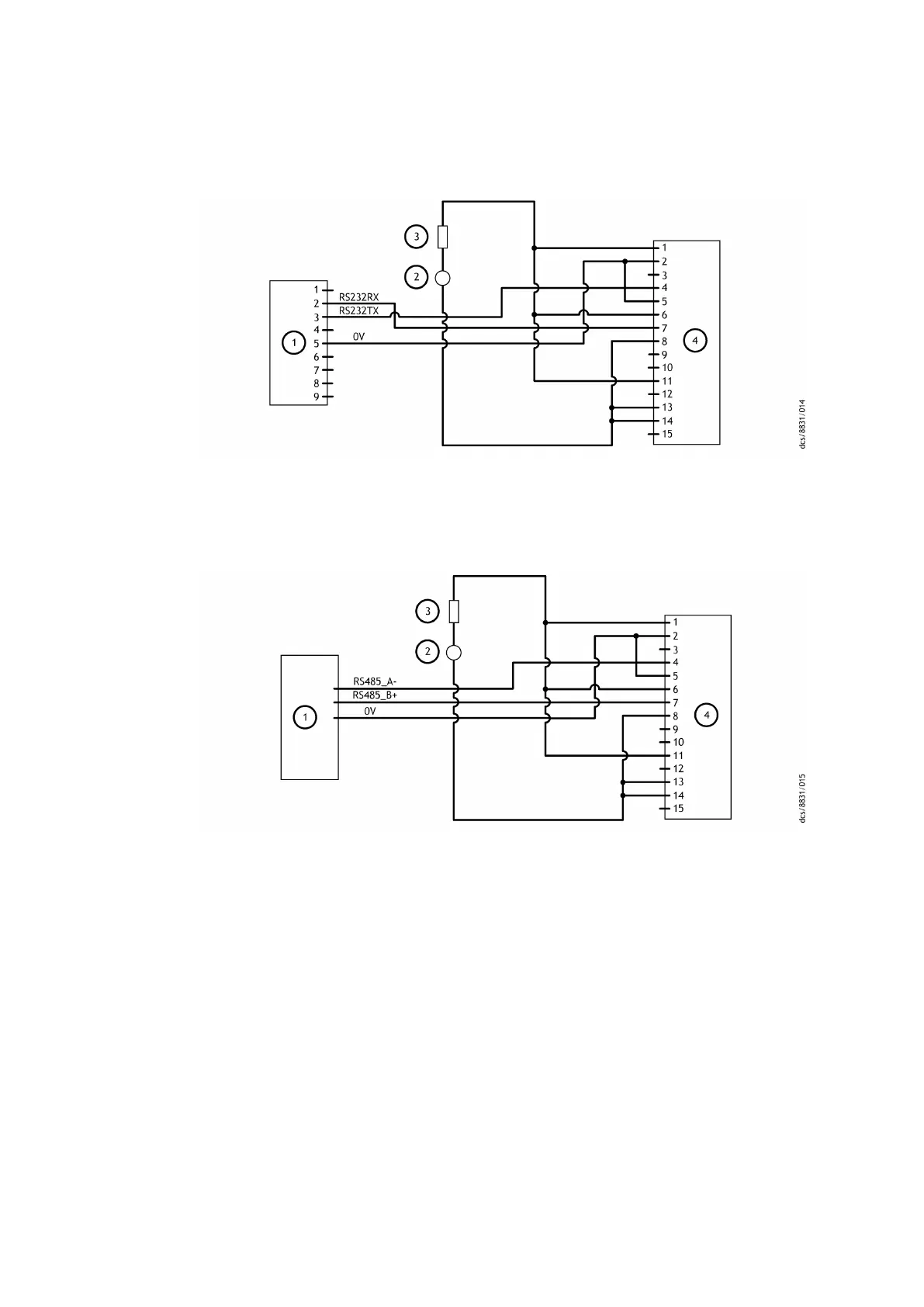
Figure 15 Logic interface connecons - RS232 serial control
1. RS232 interface on control equipment 2. 24 ‑ 48 V d.c. electrical supply
3. F
use 4. nEXT pump logic interface
1. RS232 interface on control equipment 2. 24 ‑ 48 V d.c. electrical supply
3. Fuse 4. nEXT pump logic interface
Figure 16 Logic interface connecons - RS485 serial control
1. RS485 interface on control equipment 2. 24 ‑ 48 V d.c. electrical supply
3. F
use 4. nEXT pump logic interface
1. RS485 interface on control equipment 2. 24 ‑ 48 V d.c. electrical supply
3. Fuse 4. nEXT pump logic interface
4.7.2 Serial enable
To send a serial message over the serial link, acvate the serial enable. To acvate the
serial enable, link the serial enable input signal (pin 5) to pin 2 of the customer logic
interface mang half.
We recommend you to incorporate this link into the serial communicaons cable so that
the serial enable is acvated only when the serial cable is connected. When the cable is
removed, serial enable will become inacve.
Serial enable operates as an interlock for the start commands sent over the serial
interface. If the pump operates in serial control mode (having been sent a serial start
command) and the serial enable becomes inacve, the pump will trigger a fail condion
04/2022 - ©Edwards Limited
Page 49B80000880_G
B80000880_G - Inst
allaon