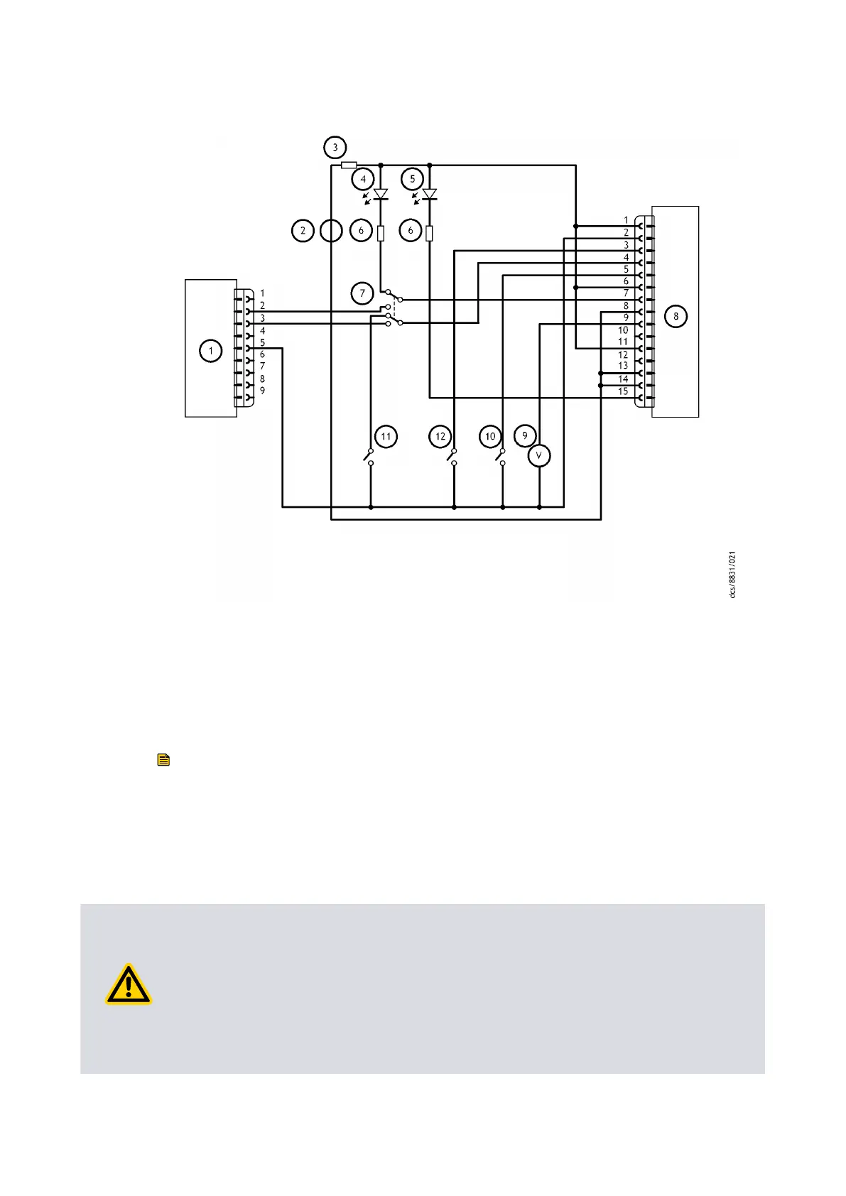
Figure 19 Logic interface connecon - mix
ed parallel and serial operaon
1. RS232 interface on control equipment 2. 24 V d.c. electrical supply
3. Fuse 4. Oponal LED indicat
or ‑ system OK
5. Oponal LED indicator ‑ normal speed 6. Current limit resistor for LED
7. Oponal serial link selector 8. pump
9. Oponal voltmeter 10. Oponal serial enable switch
11. Oponal standby switch 12. Start switch
1. RS232 interface on control equipment 2. 24 V d.c. electrical supply
3. Fuse 4. Oponal LED indicator ‑ system OK
5. Oponal LED indicator ‑ normal speed 6. Current limit resistor for LED
7. Oponal serial link selector 8. pump
9. Oponal voltmeter 10. Oponal serial enable switch
11. Oponal standby switch 12. Start switch
Note:
The volt
age supply to the pump controller can be more than 24 V. But the circuits
connected to the normal and fail line must have maximum external pull‑up voltage
rang as given in Table: Logic interface technical data.
4.9 Vent opons, vent valve connecon and control
CAUTION: RATE OF INCREASE IN PRESSURE
Risk of damage t
o equipment. If you vent the pump when it is at full rotaonal speed
and the rate of increase in pressure is too high, the pump can get damaged and its life
can decrease. We recommend to limit the rate of increase in pressure (refer to Figure:
Maximum allowed rate of increase in pressure during venng: pressure against me
(pump inially at full speed)) or open the vent valve only aer the pump speed has
decreased to 50% of the full rotaonal speed.
04/2022 - ©Edwards Limited
Page 57B80000880_G
B80000880_G - Inst
allaon