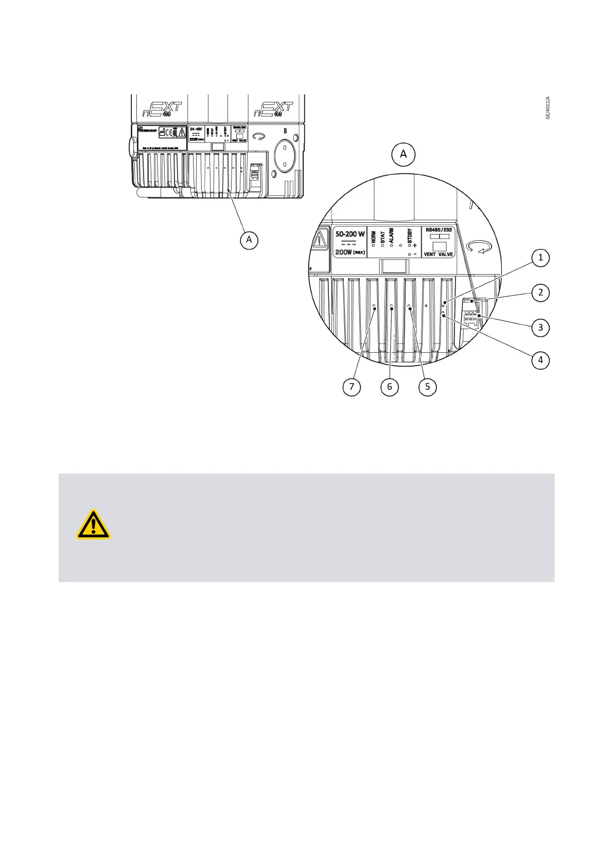
Figure 14 Controller status inf
ormaon
1. Standby speed increase buon 2. RS485 / RS232 switch
3. Controller connector socket 4. Standby speed reduce buon
5. Alarm LED 6. Status LED
7. Normal LED
1. Standby speed increase buon 2. RS485 / RS232 switch
3. Controller connector socket 4. Standby speed reduce buon
5. Alarm LED 6. Status LED
7. Normal LED
CAUTION: PUMP GROUND CONNECTION
Risk of damage to equipment. When you connect the pump to a PC, the 0 V pin on
the RS232 connector can be connected to the ground through the PC. Make sure that
the 0 V rail of the 24 ‑ 48 V d.c. supply is not connected to the ground at other point
(example, at the power supply). If the 0 V rail of the 24 ‑ 48 V d.c. supply will not be
connected to the ground at the PC, use an opto-isolated interface to the PC.
The pump can connect to the RS485 or RS232 serial input on the control equipment or a
PC as shown in Figure: Logic in
terface connecons - RS232 serial control and Figure:
Logic interface connecons - RS485 serial control. In given conguraon, the PC is the
serial link master and the pump is the slave. The distance over which the serial link will
work is dependent on the dierence in voltage between the 0 V at the sending and
receiving end. If the 0 V reference at the receiving end is in 0.3 V of the 0 V control
reference pin on the pump control connector, then the serial link has to be capable of to
operate at a distance up to 6 m. For longer distance, an interface circuit external to the
pump can be necessary.
The soware in the pump can operate with the other pumps connected to a single serial
link master. This is a mul-drop mode. The RS485 opon is recommended for the mul-
drop mode. When the RS232 opon is selected, more hardware is necessary to link
number of pump units to a single serial link master. A concept drawing of one possible
arrangement is shown in Figure: Conceptual diagram for mul‐drop connecon using
04/2022 - ©Edwards Limited
Page 48B80000880_G
B80000880_G - Inst
allaon