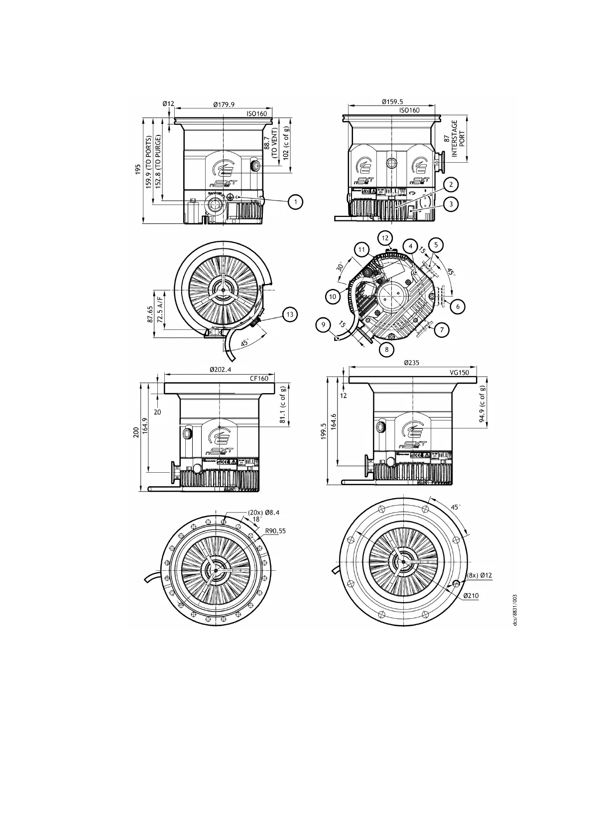
Figure 7 nEXT 400 dimensions (mm)
1. Earth point 2. LED indicators on drive unit
3. Removable cap RS485/RS232 switch vent
valve socke
t
4. Base mounng holes and fan mounngs
5. Booster port B
6. Interstage port 7. Booster port A
8. Backing port 9. 24/48 V supply
10. Body purge port 11. Electrical drive unit
12. Envelope vent port ⅛ inch BSP 13. Envelope vent
1. Earth point 2. LED indicators on drive unit
3. Removable cap RS485/RS232 switch vent
valve socket
4. Base mounng holes and fan mounngs
5. Booster port B
6. Interstage port 7. Booster port A
8. Backing port 9. 24/48 V supply
10. Body purge port 11. Electrical drive unit
12. Envelope vent port ⅛ inch BSP 13. Envelope vent
04/2022 - ©Edwards Limited
Page 26B80000880_G
B80000880_G - Technical data