GATE GENERATOR
The Gate Generator must provide an accurate, stable, signal gate to the Count Chain. The gate must be
switchable, in decade increments, between 100 micro
sec and 1 sec. The gate generator consists of a pro-
grammable divide-by-N time base
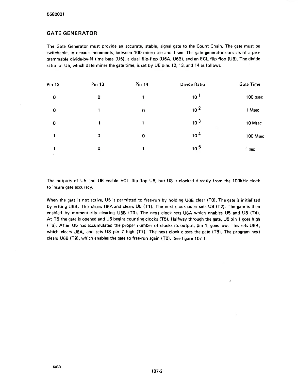
(U5), a dual flip-flop (U6A, U6B), and an ECL flip flop (U8). The divide
ratio of U5, which determines the gate time,
is
set by U5 pins 12, 13, and 14 as follows.
Pin 12 Pin 13 Pin 14 Divide Ratio Gate Time
100
psec
1 Msec
10 Msec
1 00 Msec
1
sec
The outputs of U5 and U6 enable ECL flip-flop U8, but U8 is clocked directly from the 100kHz clock
to insure gate accuracy.
When the gate
is
not active, U5
is
permitted to free-run by holding U6B clear (TO). The gate
is
initialized
by setting
U6B.. This clears U6A and clears U5 (TI). The next clock pulse sets U8 (T2). The gate
is
then
enabled by momentarily clearing U6B
(T3). The next clock sets U6A which enables U5 and U8 (T4).
At T5 the gate is opened and U5 begins counting clocks (T5). Halfway through the gate, U5 pin 1 goes high
(T6). After U5 has accumulated the proper number of clocks
its
output, pin 1, goes low. This sets U6B.
which clears U6A, and sets U8 pin 7 high (T7). The next clock closes the gate (T8). The program next
clears U6B
(T9), which enables the gate to free-run again (TO). See figure 107-1.
Scans by ArtekMedia © 2007