The POWER METER PROM (Option
02
only) contains a logic comparator
(U21),
a
2K
X
8
prom
(U20).
and a bus driver
(U19).
The logic comparator
is
connected to the microprocessor address bus,
and
is
configured to decode the
2K
address range from
4000
Hex to
47FF
Hex. The comparator
output drives the chip select of the Prom, and the bus driver. The prom contains the Power Meter
program as well as the power correction factors. Bus driver
U19
is
used as a buffer for driving the
microprocessor data bus.
PERlPHERlAL
INTERFACE
ADAPTER
(PIA)
The Peripherial Interface Adapter
(U18)
is used as the microprocessor I10 port.
It
has an address range
from
9900
Hex to
9903
Hex. Peripheral Port A is at address
9900,
and Peripheral Port B
is
at address
9902.
--------------------------
1
.z
-
P;E;ME;ER-
-
-I
ZERO DAC
I
I.
ANALOG
I
I0
MHz BUFFER TO TTL
-
100
OSCILLATOR~CONVERTER
-
I
-
I
10
MHz REFERENCE
I
-
ZERO
-
DAC
REFERENCE
I
OSCILLATOR
I
.
-
-
-
.-.
CONTROL
1w
kH* GOLK
-
I
U3tU4
GATE
GENERATOR
GATE
A
T
GENERATOR
COUPAR-
I
-
-
-
-
-
-
-
-
-
-
ATOR
-
I
-
I
BAWD
3
I
SHIFT
AMPLITUOE
-
REG
DETERMINATION
I
P U ZERO OUT
-
-
PERIPHERAL
INTERFACE
I
LATCH PM OUT
-
--
--
ADAPTOR
GATE
BUS BUS BUS
I
I
POWER METER PROM IO~tmon
02
onlvl
I
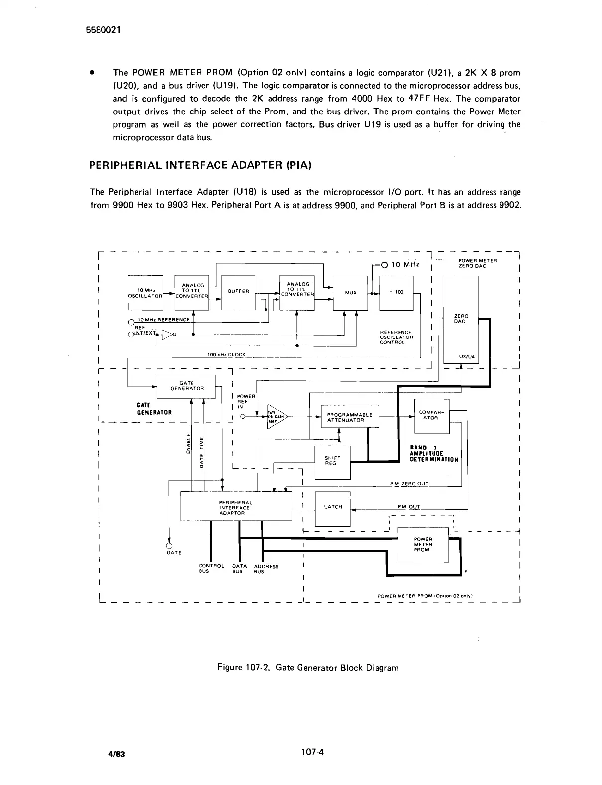
Figure
107-2.
Gate Generator Block Diagram
Scans by ArtekMedia © 2007