A1
08
CONVERTER CONTROL
(2020200)
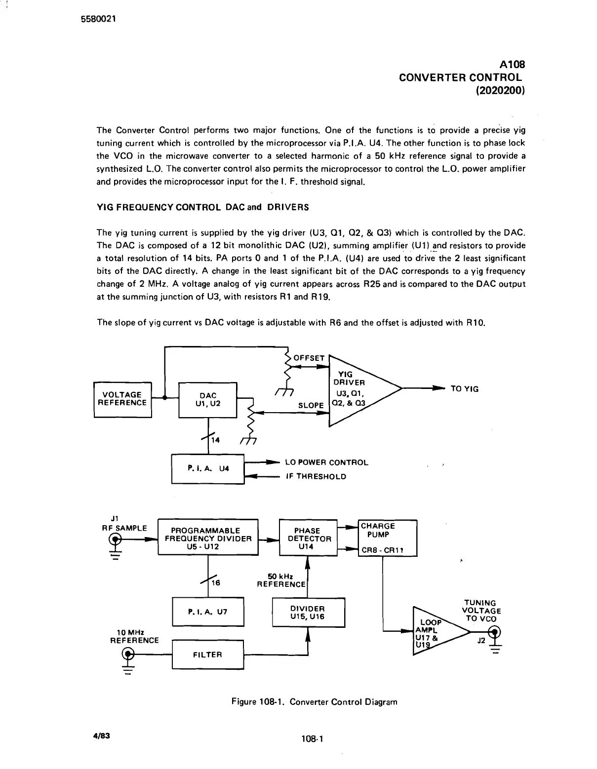
The Converter Control performs two major functions. One of the functions is
to
provide a predise yig
tuning current which is controlled by the microprocessor via P.I.A.
U4.
The other function
is
to phase lock
the VCO in the microwave converter to a selected harmonic of a
50
kHz reference signal to provide a
synthesized L.O. The converter control also permits the microprocessor to control the L.O. power amplifier
and provides the microprocessor input for the
I.
F. threshold signal.
YIG FREQUENCY CONTROL DAC
and
DRIVERS
The yig tuning current
is
supplied by the yig driver
(U3, Q1, Q2,
&
Q3)
which
is
controlled by the DAC.
The DAC
is
composed of a
12
bit monolithic DAC
(U2),
summing amplifier
(Ul)
.
and
-.
resistors to provide
a total resolution of
14
bits. PA ports
0
and
1
of the P.I.A.
(U4)
are used 'to drive the
2
least significant
bits of the DAC directly. A change in the least significant bit of the DAC corresponds to a yig frequency
change of
2
MHz. A voltage analog of yig current appears across
R25
and is compared to the DAC output
at the summing junction of
U3,
with resistors
R 1
and
R 19.
The slope of yig current vs DAC voltage
is
adjustable with
R6
and the offset is adjusted with
R10.
VOLTAGE
-. .-
1
REFERENCE ~1.~2
SLOPE Ia2,&
Q~/
L-
LO POWER CONTROL
P.
I.
A. U4
IF THRESHOLD
TO YIG
Figure
108-1.
Converter Control Diagram
J
1
RF
SAMPLE
%
-
PROGRAMMABLE
FREQUENCY DIVIDER
U5
-
U12
PHASE
DETECTOR
U14
-
+
-
CHARGE
PUMP
CR8-CR1I
50
kHz
46
REFERENCE
I
P
P.
I.
A. U7
DIVIDER
U15, U16
10 MHz
TUNING
REFERENCE
-
FILTER
-
-
Scans by ArtekMedia © 2007