VCO CONTROL
The
VCO
control, together with the
VCO,
form
a
phase lock loop frequency synthesizer. The frequency
range over which the synthesizer is used
is
from
370
MHz to
500
MHz.
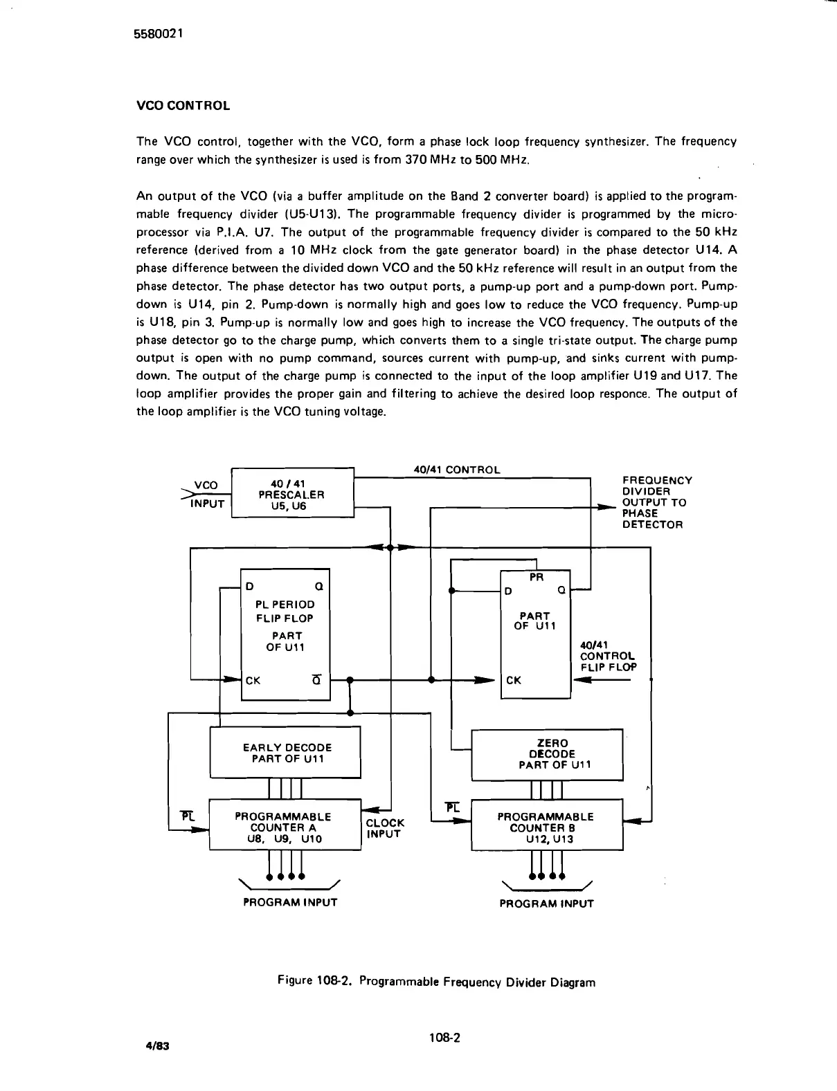
An output of the
VCO
(via
a
buffer amplitude on the Band
2
converter board)
is
applied to the program-
mable frequency divider
(U5-U13).
The programmable frequency divider is programmed by the micro-
processor via P.I.A.
U7.
The output of the programmable frequency divider
is
compared to the
50
kHz
reference (derived from
a
10
MHz clock from the gate generator board) in the phase detector
U14.
A
phase difference between the divided down
VCO
and the
50
kHz reference will result in an output from the
phase detector. The phase detector has two output ports,
a
pump-up port and
a
pump-down port. Pump-
down is
U14,
pin
2.
Pump-down is normally high and goes low to reduce the
VCO
frequency. Pump-up
is
U18,
pin
3.
Pump-up is normally low and goes high to increase the
VCO
frequency. The outputs of the
phase detector go to the charge pump, which converts them to a single tri-state output. The charge pump
output
is
open with no pump command, sources current with pump-up, and sinks current with pump-
down. The output of the charge pump
is
connected to the input of the loop amplifier
U19
and
U17.
The
loop amplifier provides the proper gain and filtering to achieve the desired loop responce. The output of
the loop amplifier is the
VCO
tuning voltage.
Figure
108-2.
Programmable Frequency Divider Diagram
Scans by ArtekMedia © 2007