SPEC1 FICATIONS,
continued
1
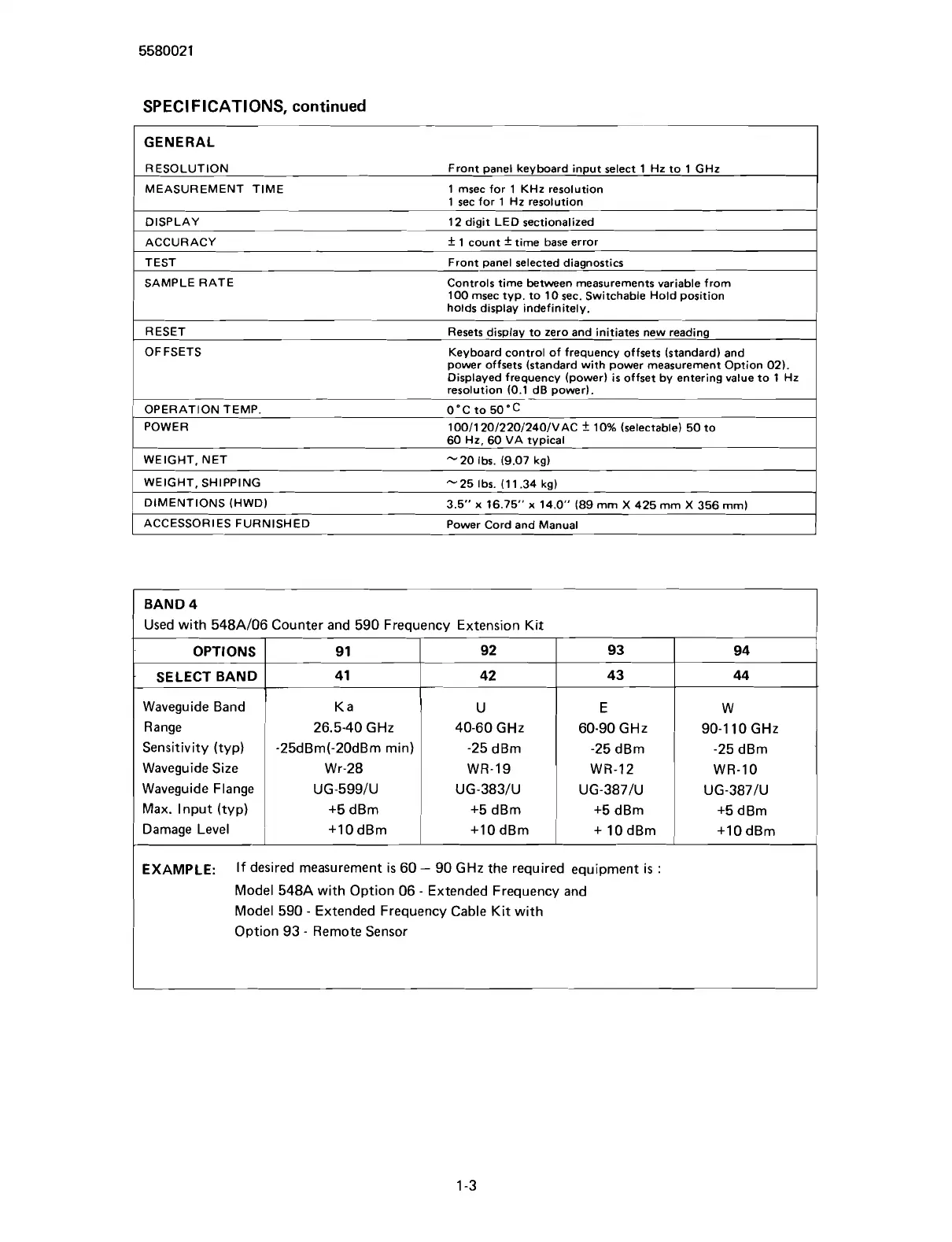
GENERAL
RESOLUTION Front panel keyboard input select 1 Hz to 1 GHz
MEASUREMENT TIME 1 msec for 1 KHz resolution
1
sec for 1 Hz resolution
DISPLAY 12 digit LED sectionalized
ACCURACY
f
1 count
f
time base error
TEST Front panel selected diagnostics
SAMPLE RATE Controls time between measurements variable from
100 msec typ. to 10
sec. Switchable Hold position
holds display indefinitely.
Resets display to zero and initiates new reading
Keyboard control of frequency offsets (standard) and
power offsets (standard with power measurement Option 02).
Displayed frequency (power) is offset by entering value to 1 Hz
resolution
10.1 dB ~owerl.
OPERATION TEMP.
O'C
to 50'C
POWER
100/120/220/240/VAC
f
10% (selectable) 50 to
60 Hz, 60 VA typical
WEIGHT, NET
-20 Ibs. (9.07 kg)
1
WEIGHT, SHIPPING -25 Ibs. (11.34 ka)
I
1
DlMENTlONS (HWD)
3.5"
x
16.75"
x
14.0" (89 mrn
X
425 mm
X
356 mrnl
I
I
ACCESSORIES FURNISHED Power Cord and Manual
I
BAND
4
Used with 548Al06 Counter and 590 Frequency Extension Kit
OPTIONS
SELECT BAND
Waveguide Band
Waveguide Flange
Max. Input
(typ)
Damage Level
1
Range
26.5-40
GHz
Sensitivity (typ) -25dBm(-20dBm min)
Waveguide Size Wr-28
EXAMPLE:
If desired measurement
is
60
-
90 GHz the required equipment is
:
Model 548A with Option 06
-
Extended Frequency and
Model 590
-
Extended Frequency Cable Kit with
Option 93
-
Remote Sensor
9
1
41
K a
40-60
GHz
-25 dBm
WR-19
92
42
U
60-90
GHz
-25 dBm
WR-12
93
43
E
90-1 10 GHz
-25 dBm
WR-10
94
44
W
Scans by ArtekMedia © 2007