A201
B
IF AMPLIFIER
(2020143)
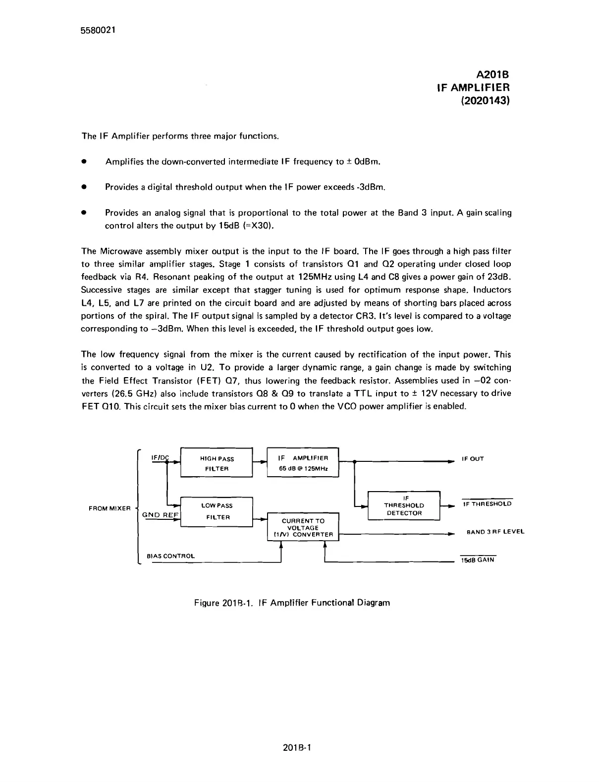
The IF Amplifier performs three major functions.
Amplifies the down-converted intermediate IF frequency to
+
OdBm.
Provides
a
digital threshold output when the IF power exceeds -3dBm.
Provides an analog signal that
is
proportional to the total power
at
the Band 3 input. A gain scaling
control alters the output by 15dB
(=X30).
The Microwave assembly mixer output
is
the input to the IF board. The IF goes through
a
high pass filter
to three similar amplifier stages. Stage 1 consists of transistors
Q1 and Q2 operating under closed loop
feedback via R4. Resonant peaking of the output
at
125MHz using L4 and C8 gives a power gain of 23dB.
Successive stages are similar except that stagger tuning
is
used for optimum response shape. Inductors
L4, L5, and L7 are printed on the circuit board and are adjusted by means of shorting bars placed across
portions of the spiral. The IF output signal
is
sampled by
a
detector CR3.
It's
level
is
compared to a voltage
corresponding to -3dBm. When this level
is
exceeded, the IF threshold output goes low.
The low frequency signal from the mixer
is
the current caused by rectification of the input power. This
is
converted to
a
voltage in U2. To provide a larger dynamic range,
a
gain change
is
made by switching
the Field Effect Transistor (FET) Q7, thus lowering the feedback resistor. Assemblies used in -02 con-
verters (26.5
GHz) also include transistors Q8
&
Q9 to translate
a
TTL input to
+
12V necessary to drive
FET
Q10. This circuit sets the mixer bias current to 0 when the VCO power amplifier
is
enabled.
FROM
MIXER
r
LOW
PASS
THRESHOLD
GND
REF
FILTER
DETECTOR
-
CURRENTTO
VOLTAGE
f1N)
CONVERTER
BAND
3
RF LEVEL
HIGH
PASS
IF
AMPLIFIER
IF
OUT
FILTER
65
dB
@
125MHz
Figure 201 8-1. IF Amplifier Functional Diagram
-
BIAS
CONTROL
I
15dBGAlN
Scans by ArtekMedia © 2007