ri
VCO 375
-
435 MHz
4
FROM
MULTIPLIER
VCO
I
I-
DC BIAS,
FVCO Xl.or FVCOX~
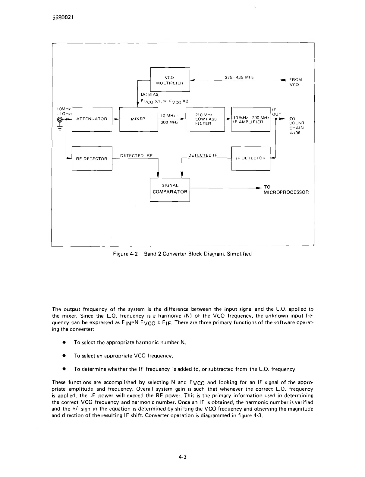
Figure
4-2
Band
2
Converter Block Diagram, Simplified
ATTENUATOR
1-
The output frequency of the system is the difference between the input signal and the L.O. applied to
the mixer. Since the L.O. frequency is a harmonic
(N)
of the VCO frequency, the unknown input fre-
quency can be expressed as
FIN=N FVCO
*
FIF. There are three primary functions of the software operat-
ing the converter:
A1 06
10 MHz
-
-
-
200 MHz
To select the appropriate harmonic number N
21 0 MHz
LOW
PASS
FILTER
RF DETECTOR
To select an appropriate VCO frequency.
10 MHz
-
200 MHz
IF AMPLIFIER
-,
v
1
To determine whether the IF frequency
is
added to, or subtracted from the L.O. frequency.
IF
OUT
u
TO
COUNT
CHAIN
DETECTED RF DETECTED IF
SIGNAL
COMPARATOR
These functions are accomplished by selecting N and FVCO and looking for an IF signal of the appro-
priate amplitude and frequency. Overall system gain is such that whenever the correct L.O. frequency
is applied, the IF power will exceed the RF power. This is the primary information used in determining
the correct VCO frequency and harmonic number. Once an IF is obtained, the harmonic number is verified
and the
+I-
sign in the equation is determined by shifting the VCO frequency and observing the magnitude
and direction of the resulting IF shift. Converter operation is diagrammed in figure
4-3.
r-
TO
MICROPROCESSOR
IF DETECTOR
4
Scans by ArtekMedia © 2007