POWER-UP RESET CI RCUlT
The power-up reset circuit consists of comparator U3 and
it's
associated components. Resistor R5 provides
hysteresis action for the circuit while
CR1 provides
a
path for fast decay time of capacitor C4.
.
CONTROL LOGIC AND BUFFERS
The
I10
select line
is
used to enable
110
chips associated with the processor system. The equation for
the selection of
110
is
:
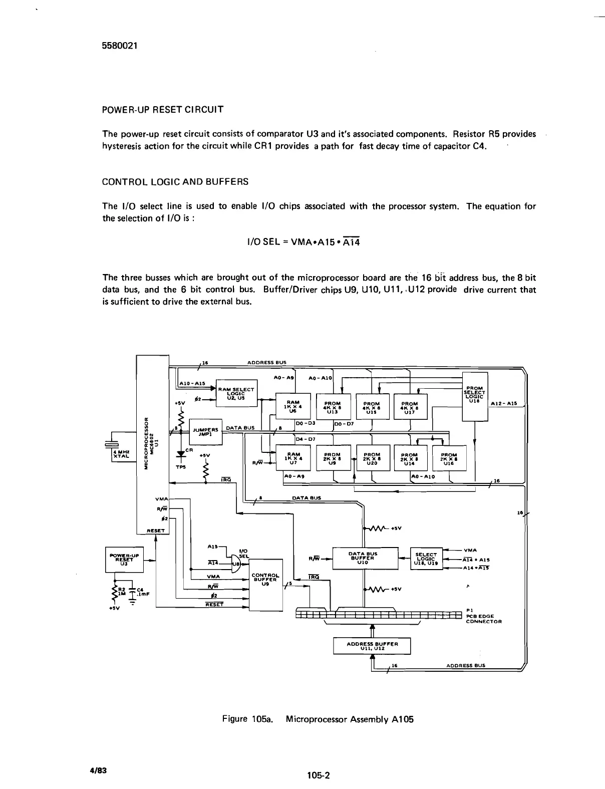
The three busses which are brought out of the microprocessor board are the 16
bft
address bus, the
8
bit
data bus, and the 6 bit control bus.
BufferIDriver chips U9, U10, U11, $U12 provide drive current that
is
sufficient to drive the external bus.
CDNNECTOR
ADDRESS BUFFER
,16
ADDRESS
BUS
Figure 105a.
Microprocessor Assembly A1 05
Scans by ArtekMedia © 2007