A1
05
MICROPROCESSOR
In the normal fetch and execute cycle, the microprocessor executes the command sequence.stored in
the PROMs and, coupled with
it's
I10
capability, obtains complete control over the counter.
The Microprocessor assembly (A1 05)
is
sectioned into four functions as follows:
1. Microprocessor
2. Memory elements
3. Power-up reset circuit
4. Control logic and buffers
MICROPROCESSOR
.
--
The MCM6802 microprocessor (Ul)
is
used as the main controlling element for the counter.
It
is
driven
by a 4 MHz crystal and controls all counter functions by means of
a
stored program in PROM.
MEMORY ELEMENTS
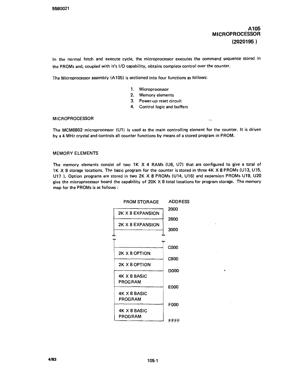
The memory elements consist of two
1K
X
4 RAMS (U6, U7) that are configured to give a total of
1K
X
8 storage locations. The basic program for the counter
is
stored in three 4K
X
8 PROMs (U13, U15,
U17
).
Option programs are stored in two 2K
X
8
PROMs (U14, U16) and expansion PROMs U19, U20
give the microprocessor board the capability of 20K
X
8 total locations for program storage. The memory
map for the PROMs
is
as follows
:
PROM STORAGE ADDRESS
2000
2800
3000
'r
2K
X
8 OPTION
2K
X
8 OPTION
4K
X
8 BASIC
PROGRAM
4K
X
8 BASIC
PROGRAM
4K
X
8 BASIC
PROGRAM
COO0
C800
DO00
€000
FOOO
FFFF
Scans by ArtekMedia © 2007