Aquastorm 200
2-10 System Preparation
SECTION 3 PHOTOCELL ADJUSTMENTS
3.1 TESTING AND ADJUSTING
THE OPTIONAL
PHOTOCELL
The Optional Photocell Sensor Emitter and
Reflector at the entrance end of the Aquastorm
200™ must be aligned to provide proper detection
of product as it enters the system.
Alignment
1 Turn on the facility power safety disonnect
for the Aquastorm 200™.
2 Press thePower On control via the
Membrane Keypad.
3 Locate the photocell emitter and reflector
at the conveyor entrance end (mounted on
the Optional Inlet Conveyor Extension).
4 Remove any objects obstructing the
emitter path.
5 Observe the green LED on the photocell
emitter.
6 Adjust the photocell emitter and reflector
so that the green indicator on the emitter
illuminates with normal movement around
the entrance end of the conveyor (see
Photocell Emitter Components
illustration).
7 Place product having the lowest
components expected to be processed, in
the path of the photocell emtter and
reflector.
8 Loosen the screws securing the photocell
emitter mounting bracket and photocell
reflector mounting bracket enough to
allow slight vertical movement.
9 Slowly lower the emitter and reflector
until the LED on the photocell emitter is
no longer illuminated.
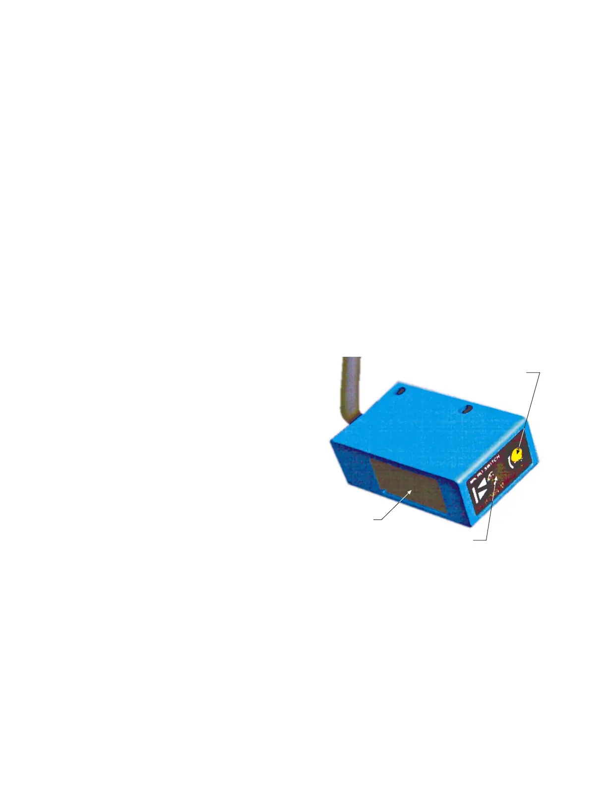
Sensitivity Adjustment Screw
Photocell Emitter
Green/ Red LED Indicator
Photocell Emitter Components
10 Secure the mounting hardware on both
the photocell emitter and photocell
reflector mounting brackets, taking
caution not to disturb the correct
placement of the photocell
components.
11 After securing the mounting hardware,
verify the green LED is still in operation
by removing product from the photocell
path.
The green LED on the photocell emitter
should illuminate when the PWA is
removed.