7 user guide
The user guide describes the power-up sequence and how to view parameters and statistics.
The user guide also describes how to:
l perform a half-reset - to clear the self learning matrix only
l run the test routine - for allrelays and inputs
7.1 power-up sequence
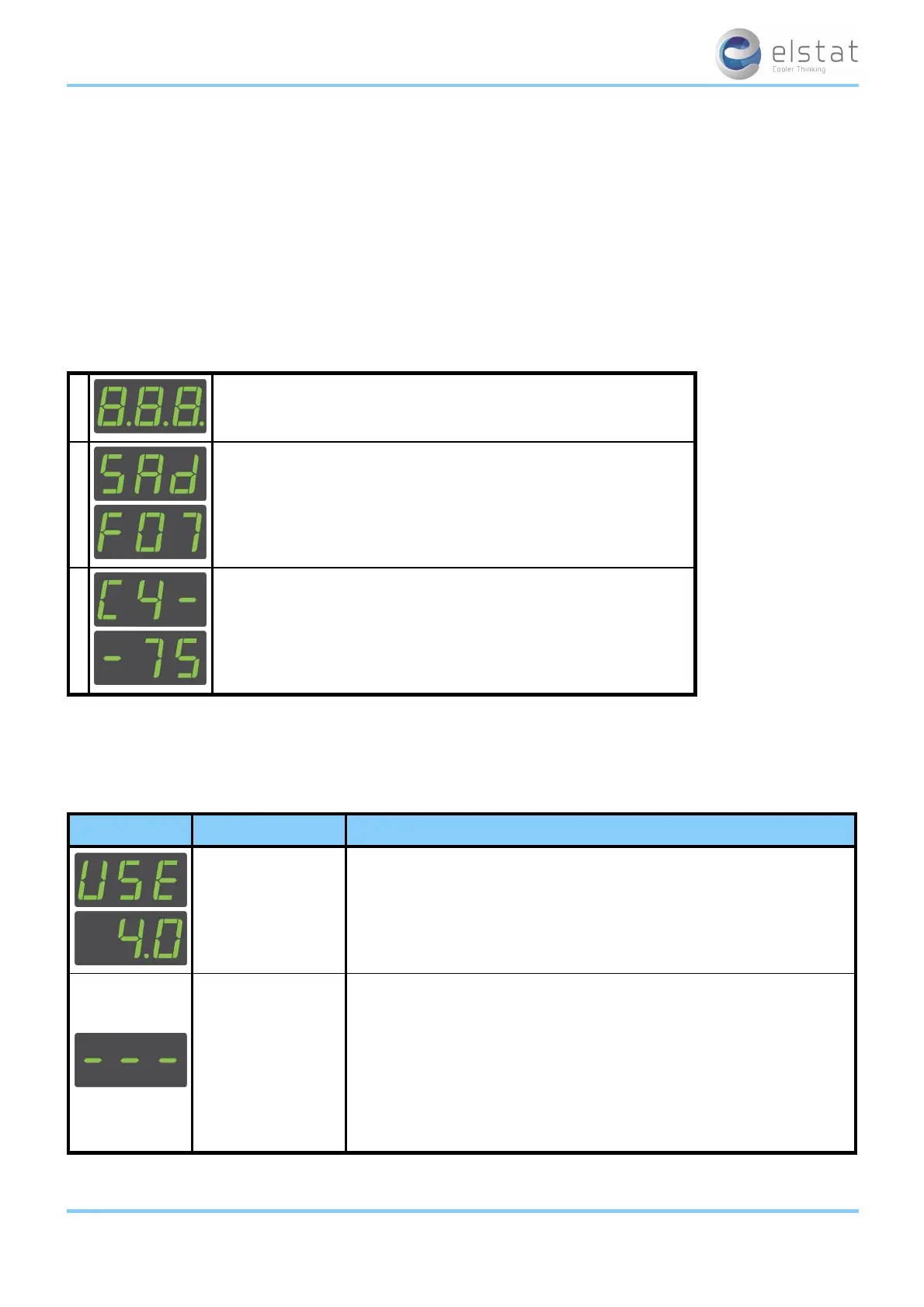
At the power up, the ems controller displays the power-up sequence as follows:
1 8.8.8. to confirm that all segments of the display are functioning correctly
2
platform type and firmware version.
(example)
3
checksum of the parameter set.
(example)
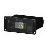
The display then shows the appropriate display code. For example, the temperature or the word USE.
7.2 display codes
The table below details the display codes for ems controllers.
display state description
ready mode
ems controllers display the appliance sensor temperature, such as 4.0, or the
word US E
Also, the cooler lights are switched on.
See "how to check that ems controllers are working correctly" on page 46
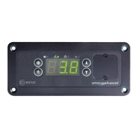
saving mode
ems controllers keep products at the saving mode
temperature unless the saving temperature is disabled.
The saving temperature LED shows whether the saving mode temperature is
disabled.
The cooler lights are off unless the light delay (Ld) parameter keeps the lights
on for a short period after the ems controller switches to the saving mode.
The marketing mode (Ar) keeps the lights on for the duration of the saving
mode.
ems25+ and ems25advanced / General Use
35 of 89