5.9 compressor management
ems controllers manage the compressor to maintain the product temperature between the set point (SP) temperature and
the set point (SP) plus differential (dI F) temperature in the ready mode or between the saving set point (SSP) temperature
and the saving set point (SSP) plus the saving differential (Sd) temperature in the saving mode.
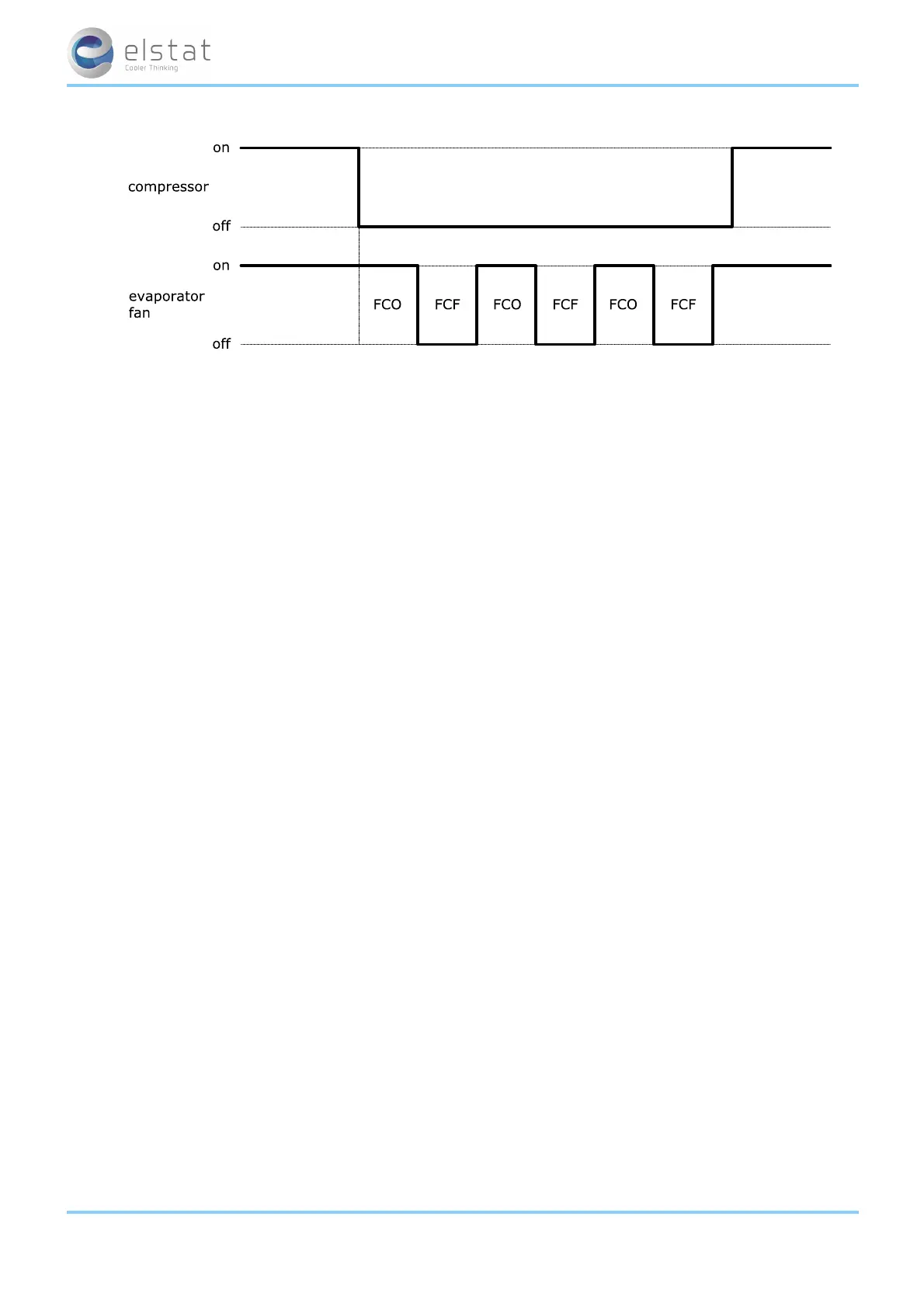
To ensure that the pressures within the refrigeration system have time to equalize during compressor off-cycles, the com-
pressor rest time (rt) defines the minimum time that the compressor can be switched off.
Compressor manufacturers usually recommend a minimum compressor rest time.
The compressor rest time (rt) helps to avoid the following:
l passing peak current through the windings of the compressor motor
l switching off the refrigeration system on the thermal overload protection
l short-cycling the refrigeration system.
However, if ready mode and saving mode differential temperatures are too small or if the compressor rest time (rt) is too
short, the ems controller cycles the compressor on the compressor rest time (rt) as the compressor rest time (rt ) over-
rides the differential temperatures.
If the compressor runs continuously for too long without reaching the set point (SP) temperature, a refrigeration system fail-
ure (rSF) alarm activates alerting to possible problems with the refrigeration system.
ems controllers can monitor the refrigeration system temperature using a condenser sensor. Monitoring the refrigeration
system temperature can help detect problems, such as a blocked condenser.
If the temperature measured on the condenser sensor reaches the condenser high temperature (Ct), the ems controller
disables the compressor and activates the (Ht) alarm. The condenser high temperature (Ct) is set by measuring the refri-
geration system temperature when the condenser is 75% blocked.
ems controllers manage the failure of a temperature sensor as follows:
l
Appliance sensor failures indicated by PF1 alarms, ems controllers stop running the compressor and then waits 60 seconds before reboot-
ing (switch off and then switch on).
If the fault continues, the ems controller repeats and continues the cycle.
l
Condenser sensor failures indicated by PF2 alarms, ems controllers continue running the compressor. ems controllers alternate the dis-
play between PF2 and the appliance sensor temperature.
l PF2 alarms may also indicate a problem with the gas cooler high temperature sensor when the cooler is a CO2 (R744) version.
An ems55advanced CO2controller willalternate between PF2 and the gas cooler
temperature sensor temperature.
l
For evaporator failures indicated by PF3 alarms, ems controllers continue running the compressor.
ems controllers alternate the display between PF3 and the appliance sensor temperature.
Note:
l Ht alarms do not apply to CO2 coolers
For more information about the parameters used in compressor management:
l See "refrigeration system failure (Ct)" on page 69
l See "differential (dIF)" on page 70
l See "compressor rest time (rt)" on page 75
l See "set point (SPC or SPF)" on page 76
l See "saving set point (SSP)" on page 76
For trouble shooting information:
ems25+ and ems25advanced / General Use
26 of 89