MES3000 Ethernet switch series 23
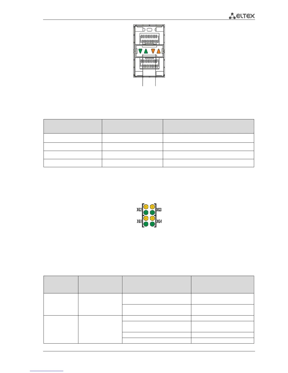
Fig. 13—SFP transceiver socket appearance
Table 2.12 —Ethernet interface status light indication
LINK/ACT indicator is lit
Port is disabled or connection is not established
10Mbps or 100Mbps connection is established
1000Mbps connection is established
Data transfer is in progress
XG interface status is represented by indicators located next to the interface sockets, see Fig. 14.
Each XG interface has a pair of associated indicators. The top ember indicator represents the activity of
the transmitting part of the port, the bottom green indicator—the activity of the receiving part of the
port. Data transmission is represented by flashing indicators of the corresponding direction.
Fig. 14—XG interface LED indicator appearance
Unit ID (1-8) indicators are intended for identifying the number of device in a stack.
System indicators (Power, Master, Fan, RPS) are designed for displaying the operation status of
MES3000 series switches.
Table 2.13 —LED indication of the system indicators and XG port indicators
Both indicators active (flashing)
(bottom—green, top—ember)
Port operation speed—
1000Mbps
Both indicators active (flashing)
(bottom—green, top—ember)
Power is on, normal device
operation
Power-on self-test (POST)
Missing primary main power