MES3000 Ethernet switch series 21
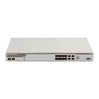
Table 2.10 —Description of connectors, LEDs and controls located on the front panel
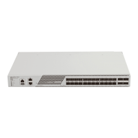
Slots for transceiver installation
For MES3100 series devices, SFP+/SFP transceivers.
For MES3224 series devices:
- XG1, XG2 slots for 10G XFP transceivers installation
- XG3, XG4 slots for 10G SFP+/ 1G SFP transceivers installation
XG optical interface activity indicator
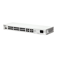
8/16/24 Gigabit Ethernet ports
For MES3108, MES3116, MES3124, MES3224 devices: 10/100/1000
Base-T (RJ-45).
For MES3108F, MES3116F, MES3124F, MES3224F devices:
1000 Base-X (SFP).
Combo ports: 10/100/1000 Base-T (RJ45).
Indicator of device number in stack.
Device activity mode indicator (master/slave).
Backup power supply indicator.
Functional key that reboots the device and resets it to factory
settings:
- pressing the key for less than 10 seconds reboots the device.
- pressing the key for more than 10 seconds resets the device to
factory settings.
RS-232 console port for local control of the device.
2.4.2 Rear panel of the device
The rear panel layout of MES3000 series switches is depicted in Fig. 9
.
Fig. 9—Rear panel of MES3000
The figure shows delivery package of a switch equipped with 1 x DC power supply and 1 x AC power supply.