8. Secure the auto cleaner with the lower screw M6x20 and tighten both screws.
.
9. Disconnect the 24VDC, oven sensor and CAN bus line in the analyser and let it hang down
to the side outside the device.
10. Take the control assembly of the auto cleaner and connect the compressed air line P4
with the control assembly.
11. Connect the compressed air line P4A with the valve unit of the analyser’s oven.
12. Insert the control assembly. Ensure that no lines get caught or cut off. The compressed
air line P4 should be routed below the pressure reducer.
13. Secure the control assembly to the aluminium profile with the pre-assembled screws and
sliding blocks.
14. Connect the electrical connections of the auto cleaner to the control assembly, paying
attention to the colour coding.
15. Secure the cable with the already fitted cable tie.
16. Connect the 24VDC supply line to the control assembly.
17. Connect the CAN bus line to the control assembly.
18. Remove the tape from the auto cleaner and carefully slide the auto cleaner down.
19. Turn the arm of the auto loader by hand into the open oven area of the analyser.
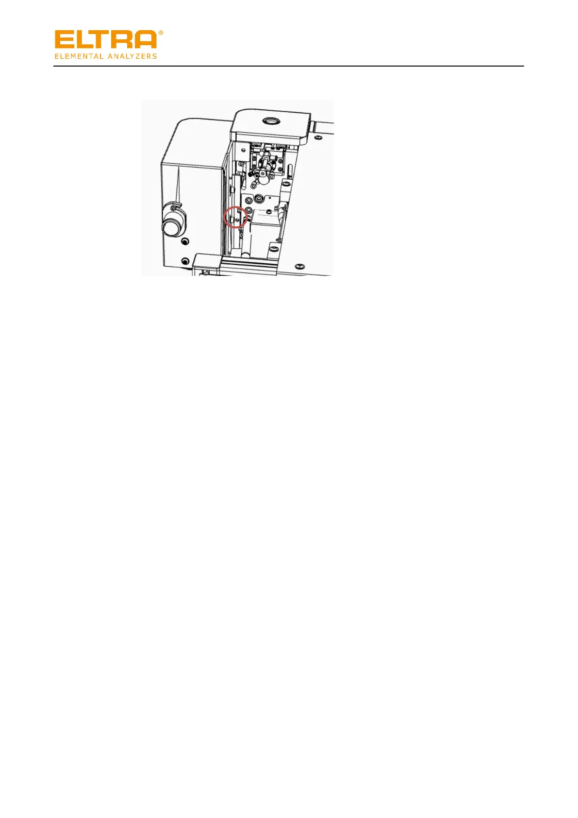
20. Carefully loosen the two screws slightly (do not unscrew completely).

 Loading...


