Cabling Control Station, modem, and public LAN
Your system might contain one or two Control Stations. If you have one CS, it is called the
primary Control Station or CS0. If you have a second or optional CS, it is called the
secondary Control Station or CS1.
Cabling CS0
Procedure
1. If you have not removed the labels from the front of CS0 and CS1 (if applicable),
remove them now and attach to the inside front cover of this document.
2. Locate the cables shown in Figure 25 on page 42. You already connected extension
cables (labeled CS0 B and CS0 MGMT) when you installed the Control Station.
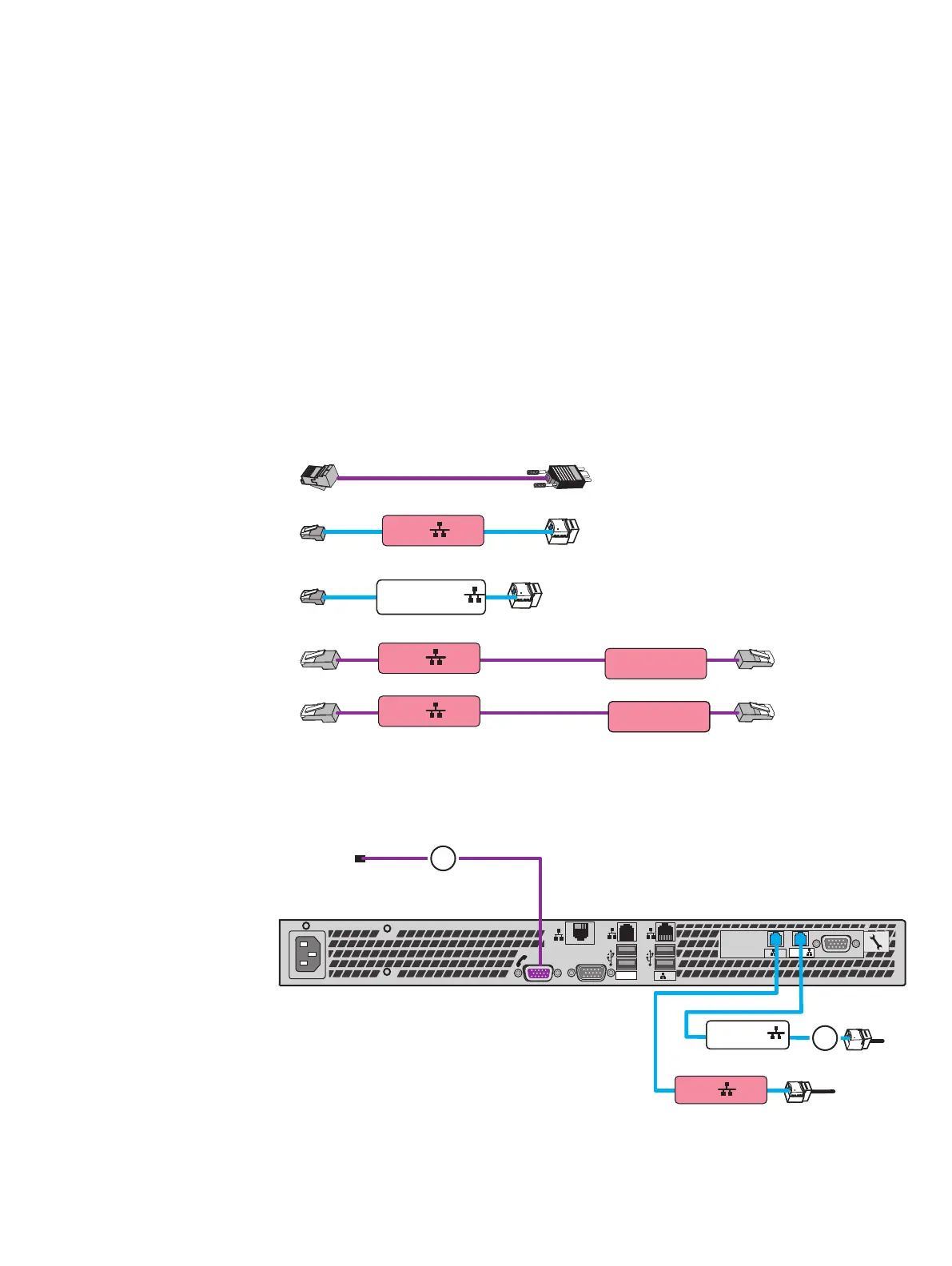
Figure 25 CS0 cables
CS0 A
Blade Encl 0
MMA Port 1
CS0 B
Blade Encl 0
MMB Port 1
CS0 B
CS0 MGMT
3. Connect the CS0 to your network environment:
Refer to Figure 26 on page 42 while performing the procedure that follows.
Figure 26 Cabling CS0 to modem and public LAN
B MGMT
MGMT
B
CS
A
1
2
MGMT
IOIO
CS0 B
CS 0 MGMT
1
2
a. Connect your public LAN using a CAT5e or better Ethernet cable (customer
supplied) to the CS0 MGMT extension cable (cable 2).
Cable your system
42 EMC VNX Series VNX5600 Unified Installation Guide

 Loading...


