b. Connect CS0 to the customer modem, if applicable (cable 1).
4. Connect CS0 to blade enclosure 0:
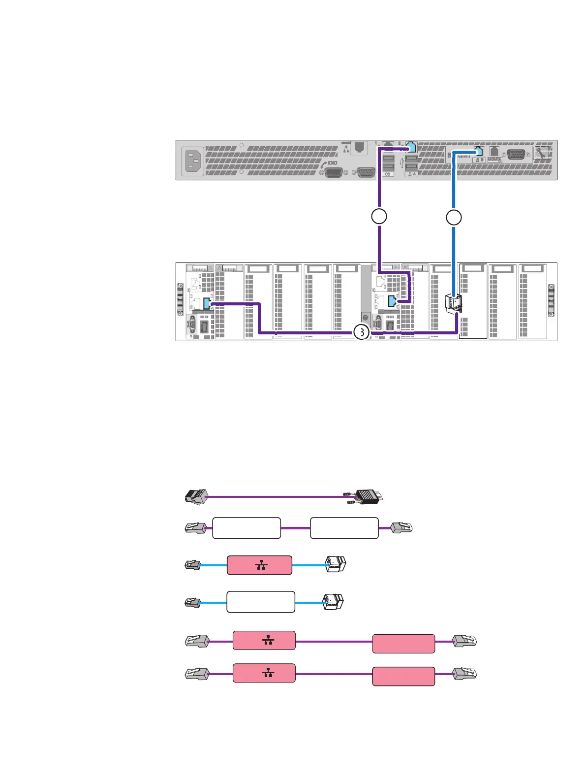
Refer to Figure 27 on page 43 while performing the procedure that follows.
Figure 27 Cabling CS0 to blade enclosure 0
a. Connect CS0 A cable to Blade Enclosure 0 MMA port 1 (cable 1).
b. Connect CS0 B cable to Blade Enclosure 0 MMB port 1 (cables 2 and 3).
Cabling CS1 (optional)
Procedure
1. Locate the cables shown in Figure 28 on page 43. You already connected extension
cables (labeled CS1 B and CS1 MGMT) when you installed the Control Station.
Figure 28 CS1 cables
CS0 CS Port
CS1 CS Port
CS1 A
Blade Encl 0
MMA Port 2
CS1 B
Blade Encl 0
MMB Port 2
CS1 B
CS1 MGMT
2. Connect the CS1 to your network environment:
Refer to Figure 29 on page 44 while performing the procedure that follows.
Cable your system
Cabling CS1 (optional) 43

 Loading...


