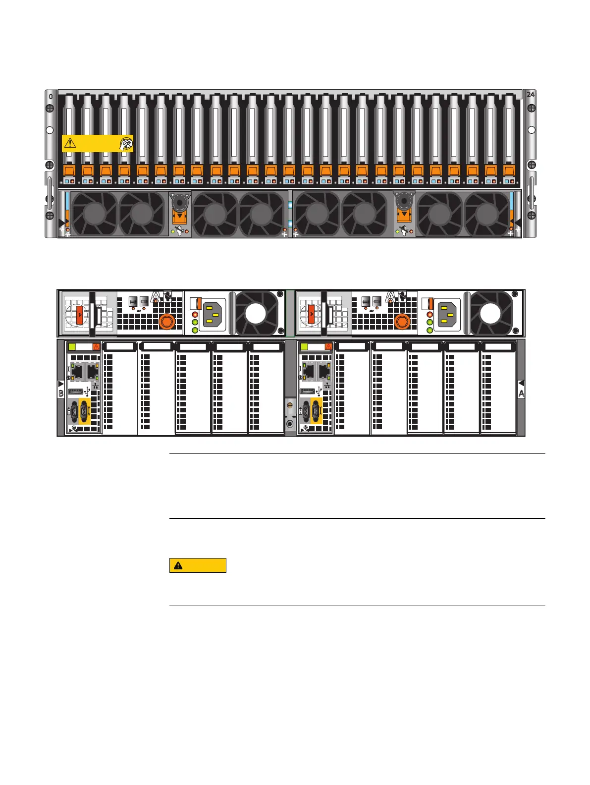
Figure 14 Front and rear view of DPE
Front
Disk-processor enclosure (Jetfire)
A
B
SP
SP
Will Make the Array Unusable
Caution: Array Software on drives 0-3. Removing or relocating them
01
01
AC
DC
!
1
0
1
0
X4
AC
DC
!
X4
X4
X4
AB
The DPE contains two storage processors (SP A and SP B). Each SP contains a
management module and five slots for I/O modules, numbered 0-4. SP slots that do not
support I/O modules are labeled.
Installing the disk processor enclosure
DO NOT lift the DPE by its I/O module handles. Use two people to lift the DPE on each
side.
Refer to Figure 16 on page 33 while performing the procedure that follows.
Procedure
1. Locate the Product ID/SN from the product serial number tag (PSNT) located on the
back of the DPE as shown in Figure 15 on page 32.
Assemble components in your cabinet
Installing the disk processor enclosure 31

 Loading...


