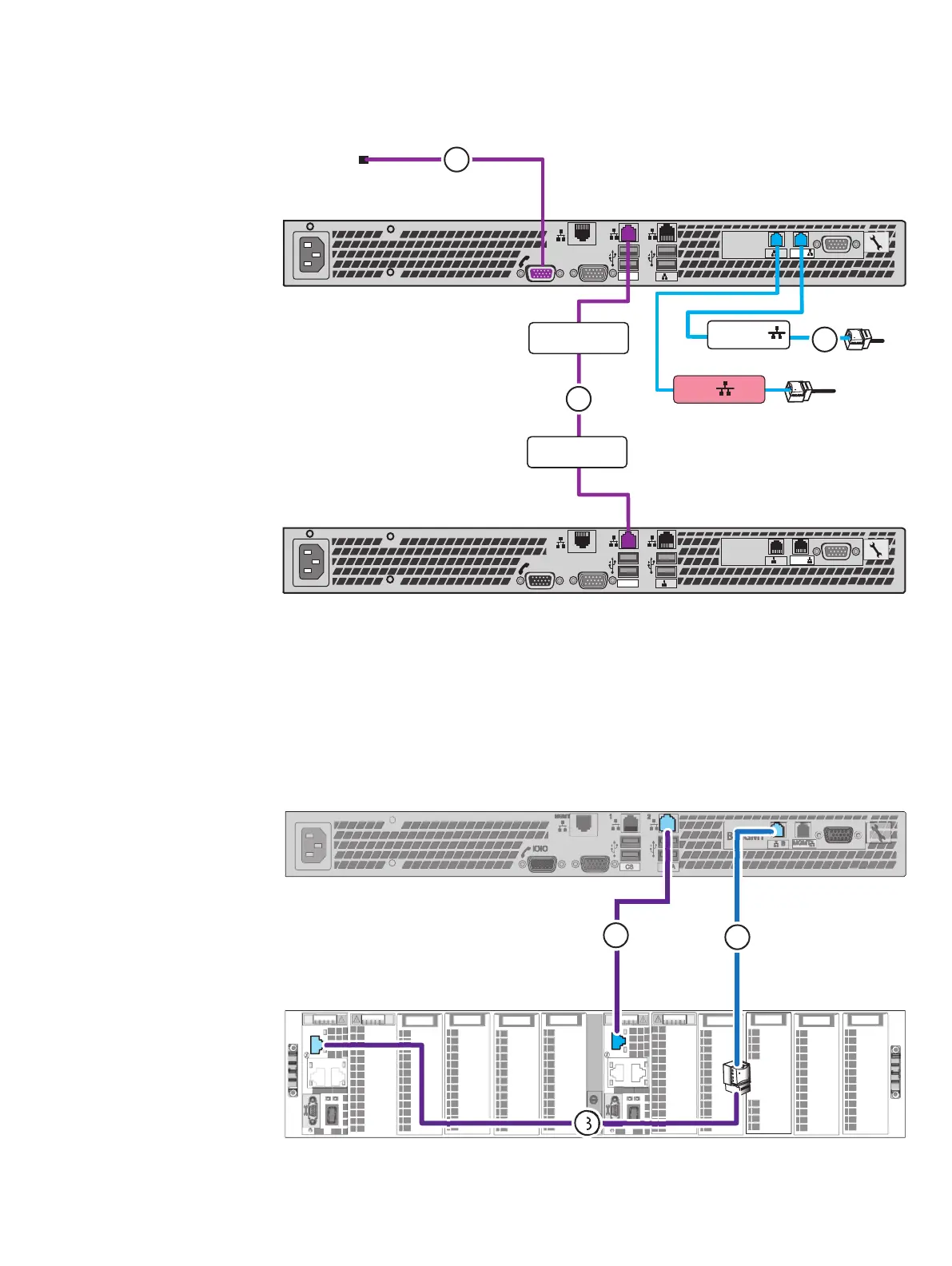
Figure 29 Cabling CS1 to modem and public LAN
B MGMT
MGMT
B
CS
A
1
2
MGMT
IOIO
B MGMT
MGMT
B
CS
A
1
2
MGMT
IOIO
CS 1 MGMT
CS1 CS Port
CS0 CS Port
3
CS1 B
1
2
a. Connect CS1 to the customer modem, if applicable (cable 1).
b. Connect CS1 Intelligent Platform Management Interface (IPMI) to CS0 (cable 2).
c. Connect your public LAN using a CAT5e or better Ethernet cable (customer
supplied) to the CS1 MGMT extension cable (cable 3).
3. Connect CS1 to blade enclosure 0:
Refer to Figure 30 on page 44 while performing the procedure that follows.
Figure 30 Cabling CS1 to blade enclosure 0
a. Connect CS1 A cable to Blade Enclosure 0 MMA port 2 (cable 1).
Cable your system
44 EMC VNX Series VNX5600 Unified Installation Guide

 Loading...


