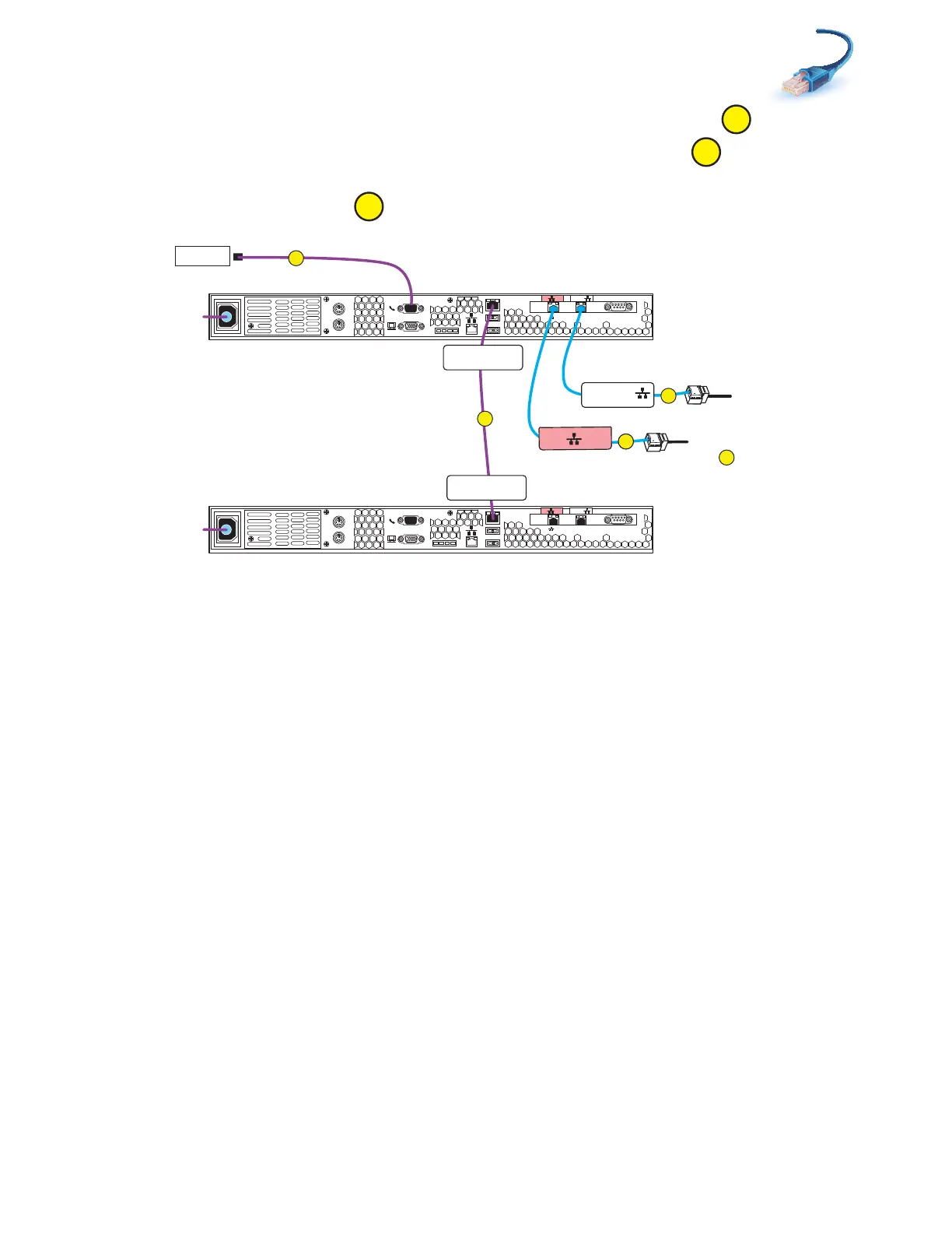
Cabling Control Station, modem, and public LAN
31
2. Connect CS1 to the customer modem, if applicable as shown in Figure 18.
3. Connect CS1 Intelligent Platform Management Interface (IPMI) to CS0.
4. Connect your public LAN via a CAT5e or better Ethernet cable (customer supplied) to the CS1
MGMT extension cable.
Figure 18 Cabling CS1 to modem and public LAN
Serial
console
MGMT
CS
B
MODEM socket
VGA plug
A
IPMI port
Serial
console
MGMT
CS
B
MODEM socket
VGA plug
A
IPMI port
B
MGMT
B
B
MGMT
CS1 CS Port
CS0 CS Port
Modem
PDU A
PDU B
Control Station 0
Control Station 1
Rear
CS1 B
CS1 MGMT
C
D
Cable to public LAN
To cable
to
Blade Encl 0 MMB Port 2
F
C
B
A
VNX-000204
 Loading...

