User Instructions
MAN-02-04-60-0350-EN Rev. 3 February 2019
26
Section 6: Control Unit
Control Unit
Section 6: Control Unit
The controller is intended to monitor and control the actuator and provides the interface
between the operator, the control system and the actuator.
6.1 Operating Unit
Operation relies on two switches: the control switch and a padlock-protected selector
switch. Information visualization is provided by 4 integrated indicator lights, as well as the
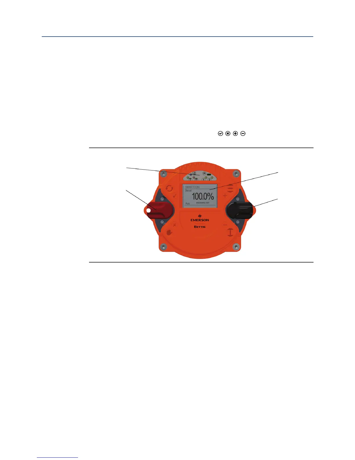
graphic display. For better visibility, switch symbols ( , , , ) are on the cover.
Figure 29 Operating Unit Controls
4
1
3
2
Display Overview:
1. Selector switch
2. Control switch,
3. Graphic display,
4. LED display
The controller switches serve on the one hand for electric-motor operation of the actuator
and, on the other hand, to congure and view various menu items.
The controller cover may be wiped clean with a damp cloth.
The mounting position of the control unit can be turned in 90° steps (see Section 4.4).
 Loading...


