User Instructions
MAN-02-04-60-0350-EN Rev. 3 February 2019
82
Section 16: Technical Data and Certifications
Technical Data and Certications
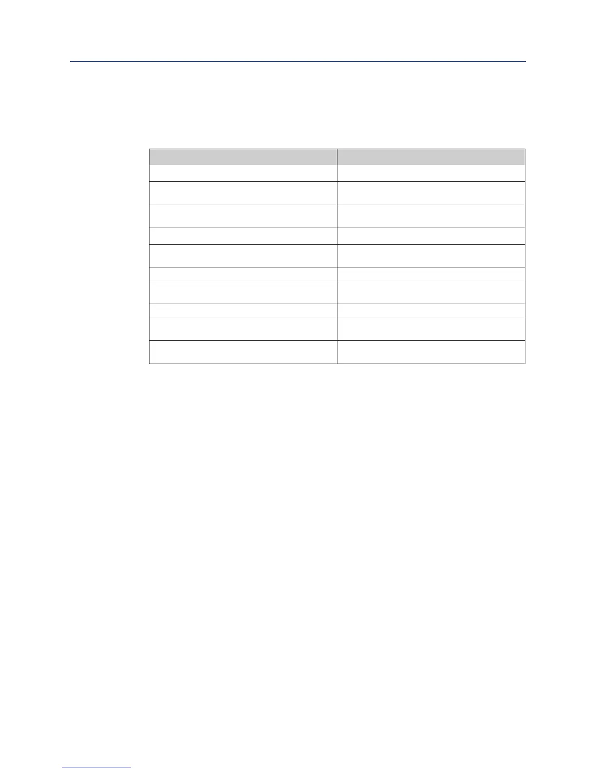
16.5 Auxiliary Voltage Input and Output
Table 37. Auxiliary voltage input and output
Characteristic Value
Input voltage range (auxiliary voltage input) 20. . . 30VDC
Maximum current consumption
(auxiliary voltage input)
500mA
Maximum current consumption in power-save
mode (auxiliary voltage input)
120mA
Output voltage (auxiliary voltage output) typ. 23 V
Maximum output current (auxiliary voltage
output)
200mA
Resistance of common ground vs. earth typ. 500 k Ohms
Resistance of common ground vs. earth
(oating version)
> 10M Ohms
Capacitance of common ground vs. earth typ. 100 nF
Maximum allowed voltage of common ground
vs. earth
max. 40 Vs
Fuse (Fuse F1, see Figure 63)
1 A slow
(Littelfuse 454 NANO2 Slo-Blo R )
Ground potential is the common ground of the controller and the analog inputs
and outputs.
The auxiliary voltage output can be set in menu P6.5 (see Section 7.5).
The power-save mode is dened as follows:
• No power supply (the controller is powered exclusively through the 24V auxiliary
voltage input).
• The backlight of the LCD display switches off automatically.
• No additional hardware options included (Probus Interface, DeviceNet interface,
relay board, etc.).
• Binary outputs and the mA output are not enabled; when activating, the
respective currents must be added to the total current consumption.

 Loading...


