User Instructions
MAN-02-04-60-0350-EN Rev. 3 February 2019
84
Section 16: Technical Data and Certifications
Technical Data and Certications
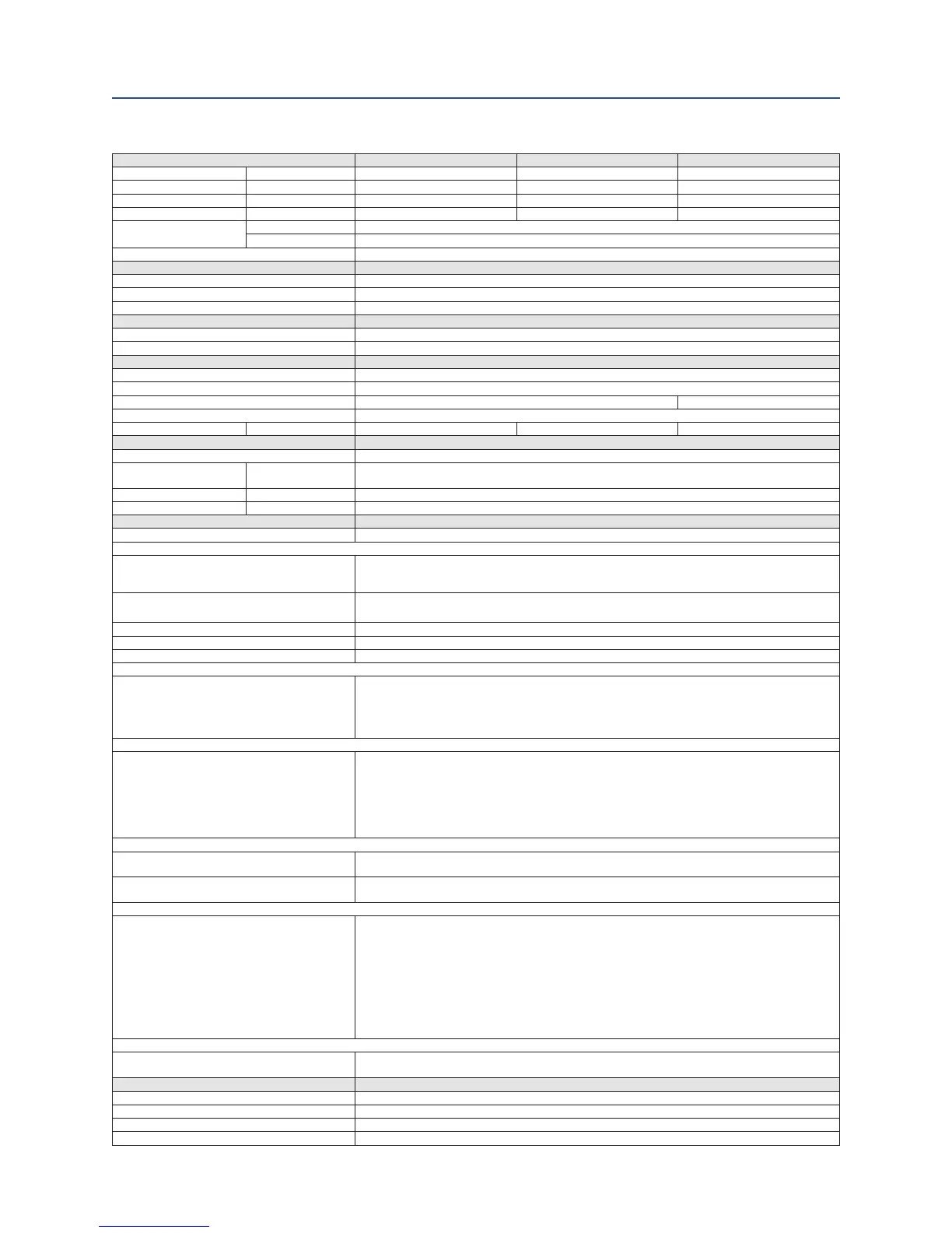
TYPE CL-05 CL-15 CL-25
Max Thrust (Adjustable) lbs. (kN) 3327 (15) 3327 (15) 5620 (25)
Max Modulating Force lbs. (kN) 1798 (8) 1798 (8) 3327 (15)
Adjustable Positioning Speed mm / sec 0.17 - 4.7 0.17 - 4.7 0.17 - 4.7
Max Stroke Length inch (mm) 1.96 (50) 3.93 (100) 3.93 (100)
Operation Mode
On/Off duty S2
Modulating duty S9
Manual Operation Automatic declutch for manual operation
VALVE-MOUNTING
Flange F10 (ISO 5210)
Stem Thread M16 x 1.5
Rotation Stem of linear unit extends with clockwise handwheel rotation
OPERATING CONDITIONS
Ingress Protection IP66, IP67
Ambient Temperature -40°C to + 60°C
HOUSING
Material Aluminum
Enclosure Weather-proof / Explosion-proof (optional)
Certication 1ph, 24VD – CSA NEC 500 / NEC505, ATEX, IECEx, LVD 3ph - ATEX 1ph, 24VD – CSA NEC505, ATEX
Coating High quality two component polyurethane paint system-C3 ISO12944-5
Approximate Weight lbs. (kg) 27.5 (12.5) 36.3 (16.5) 44 (20)
MOTOR Brushless DC Motor
Isolation Class
Power Supply V
24 - 230 VDC *, Single Phase 115V - 230V +/-10%, Three Phase 380V - 480V +/-10%
(*restrictions apply)
Current Consumption A 2.25
Power W 250
ACTUATOR CONTROL
Technology Integrated processor control unit with frequency-technology for variable speed control
Control Unit
Control Elements
· Selector switch LOCAL - OFF- REMOTE (lockable)
· Control switch OPEN - STOP - CLOSE contact less sensor technology
· Language independent symbols
Control Functions
· Full stroke test
· Partial stroke test
Local Display Backlit LCD display, can be rotated in 90 degree increments
LEDs Programmable LED's for operation, readiness, warning and error messages
Communication Infrared & Bluetooth communication interface for programming and saving operation data
Control
Inputs
· 5 congurable binary (discrete) control inputs:
OPEN - STOP - CLOSE - EMERGENCY OPEN - EMERGENCY CLOSE
· Power supply: 24VDC (max 30VDC) - current consumption with 24VDC: typical 5mA
· Optically isolated inputs
· Analog control 4-20 mA (2 wire)
Status Indication
Outputs
· 8 congurable binary output relays for status:
READY - OPEN - CLOSE - RUNNING OPEN - RUNNING CLOSE - TORQUE - LOCAL - REMOTE
· Power supply 24VDC +/- 6V (per actuator or through control system)
· Max allowed current per output: 50mA (short-circuit-proof)
· Max allowed current for all outputs with power supplied by actuator: 150mA
· Max allowed current for all outputs with power supplied by control system: 250mA
· All outputs are optical isolated if power is supplied by control system
Voltage Input and Output
Power Supply - External
· Input power range: 20-30VDC max current consumption 320mA or 100mA in current save mode
· Status indication also in case of a main power supply failure
Power Supply - By Actuator
· Output voltage: typical 22V max output current 150mA
· Reference ground is the common ground of the control unit and of the analog inputs and outputs
Functions
Standard
· Switch-off mode adjustable: travel or torque dependent to valve type
· Torque/Force adjustable: 25-100% of max torque/force
· 4 intermediate positions between 0 and 100% in both directions parametrizable
· Variable Speed operation with adjustable speed proles independent of direction.
Congurable proles for Local – Remote – ESD scenarios.
· PID positioner for 2 input signals 0/4-20mA (setpoint, external actual value)
· Writing and reading protection via password
· Multilingual display indication: German, English, Czech, Russia and Danish
· Status indication of binary inputs and outputs including analog signal values on LCD display
· Data logging for analysis and service
Electrical Connections
Cable Entries
3 metric threaded holes for cable glands: Weather-proof 1xM40, 1xM32, 1xM25 /
Explosion-proof 1xM40 + 2xM20
OPTIONS
Digital Communications Modbus RTU, ProBus, ProNet, Foundation FieldBus HART Platforms
Relay Board 250 VAC, 2A with 4 outputs
Analog Position Transmitter 0/4-20mA (2-wire)
Coating 4 layer with Epoxy under coat for increased corrosion protection – C5-I, C5-M ISO12944-5

 Loading...


